2. System component
10
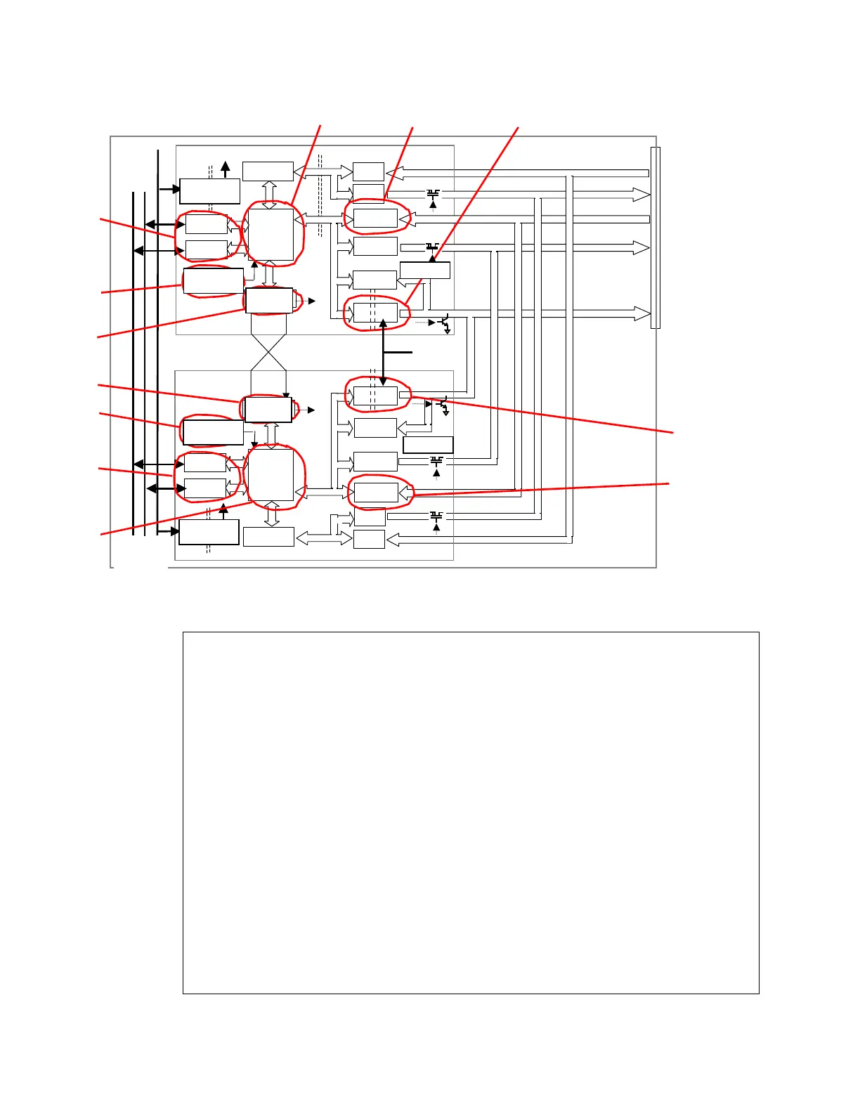
Fig. 2.4 SLP05 module internal circuit
●
Diagnosis circuit
(1) CPU operation monitoring with WDT
(2) Online ROM/RAM check
(3) 5V power monitoring
(4) I/O bus transmission diagnosis
(5) A/D conversion circuit reference input voltage diagnosis
(6) Analog input value comparative diagnosis
(7) MV read-back diagnosis
(8) Redundancy changeover status diagnosis
*1 For the D/A conversion part (analog input part), failure detection of the input protection part (each
channel independent) can be done by comparative diagnosis of analog input values by SBIF3.
However, failure detection cannot be done for single configuration.
*2 For important parts, state monitoring at the application level and failure diagnosis at the system
level are recommended.
*3 Failure diagnosis may not be done for some parts. Also, errors may not be detected even for
the target parts of failure diagnosis depending on the failure mode. A power on/off test and
redundancy changeover test are recommended upon periodic repair.
CPU
A/D
D/A
A/D
AI1~6
D/A
AO1~2
MV1~4
MV
CPLD
DI
DO
DI1~4
DO1~4
D/R
D/R
リードバック
切替制御
D/A
A/D
D/A
A/D
DO
DI
CPU
切替制御
CPLD
D/R
D/R
I/Oバス
バスA
バスB
SLP05
(SCD)
SLP05
(PRM)
ULCU11
リードバック
MV
電源 Reg.
電源監視
電源
Reg.
電源監視
24V
①②
③
④
④
⑤⑥
⑤⑥
⑦
⑦
③
①②
⑧
⑧
MV power
supply 24V
ULCU12
System power
supply 24V
Bus A
Power supply
Reg.
Power supply
Monitoring
Changeover
control
MV read-back
Power supply
Monitoring
Changeover
control
Power supply
Reg.
MV read-back
I/O bus
Bus B
 Loading...


