3. Installation and wiring
20
Table 3.3 Recommended minimum separation distance
(when metal ducts with lid and metal ducts are used)
Total parallel distance
Cable power
10m or less 25m or less 100m or less
125V or less 10A or less 10 or more 10 or more 50 or more
250V or less 50A or less 10 or more 50 or more 150 or more
400V or less 100A or less 50 or more 100 or more 200 or more
500V or less 200A or less 100 or more 200 or more 250 or more
More than the above 500 or more
(Unit: mm)
Grounding
As a rule, the DPCS/E housing is isolated from the installation floor face using an insulator.
If isolation is not possible due to unavoidable reasons, observe the following precautions.
(1) Isolate the DPCS housing from the installation floor face.
(2) If it is not possible, isolate the entire components from the housing upon installation, and
ground them to the dedicated grounding.
Insert insulating washers between the in-control system (base unit), loop system (base
unit, marshaling unit), loop system (base unit) and other components (distribution unit,
line filter, etc.) and the housing frame when installing them to the housing.
In this case, connect each components to the dedicated grounding line without looping
the IV line.
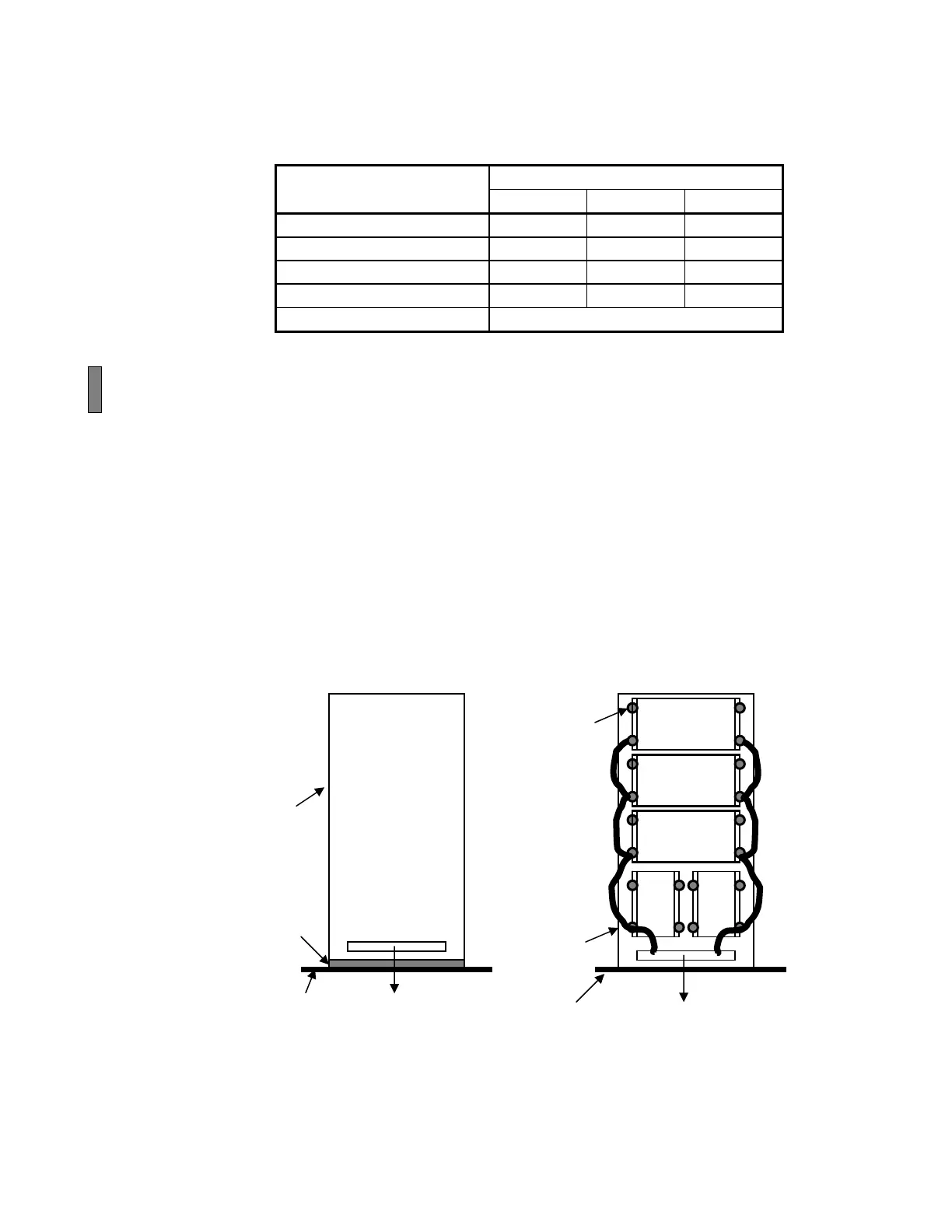
Fig. 3.1 DPSC/E housing grounding diagram
Housing
Installation floor face
Insulating
washer
To the dedicated
grounding line
Insulating
material
Installation floor face
Housing
To the dedicated
grounding line
Example of (1) Example of (2)
Main system
base unit
Loop system
base unit
I/O system
base unit
Marshaling unit
 Loading...


