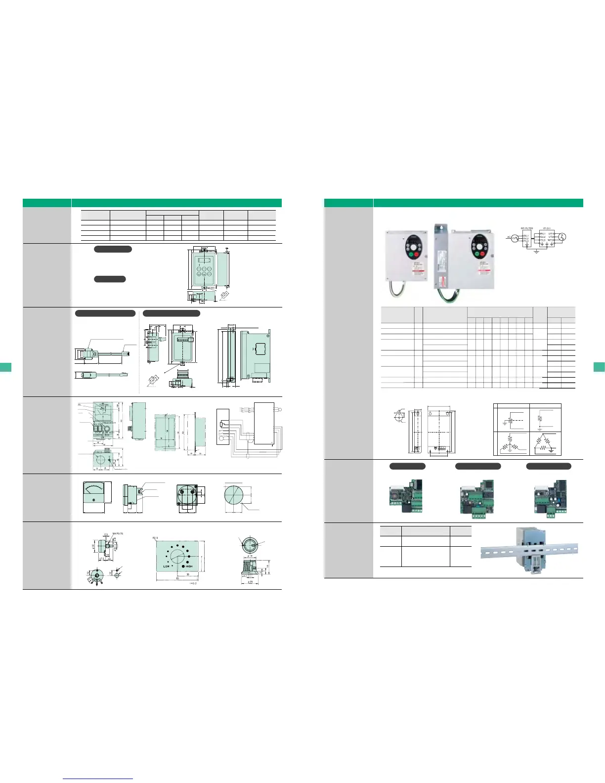
Peripheral devices
20
Devices External dimensions and connections
EMC noise
reduction filter
(Compliant with
European
standards)
Internal
communication
card
DIN rail kit
RS485 DeviceNet LONWORKS
Side mount installation
How to wire
Power source A Power source B
Type
Rated
current
Inverter type
Approx.leakage
current(mA)
Note 1)
Approx.
weight
(kg)
Dimensions(mm)
WHDW1H1E F G
9
7
16
15
22
25
47
83
49
EMFS11S-2009AZ
EMFS11-2007AZ
EMFS11S-2016BZ
EMFS11-4015BZ
EMFS11S-2022CZ
EMFS11-4025CZ
EMFS11-4047DZ
EMFS11-2083EZ
EMFS11-4049EZ
37
37
35
42
35
50
60
80
60
195
195
195
195
235
235
305
395
395
72
72
105
105
140
140
180
245
245
52
52
85
85
120
120
140
205
205
180
180
180
180
215
215
285
375
375
5
5
5
5
5
5
5.5
5.5
5.5
8.5
8.5
8.5
8.5
8.5
8.5
9.5
9.5
9.5
10
10
10
10
10
10
11
11
11
47
45
47
48
96
103
125
249
147
293
104
293
Power
source A
Power
source B
3
7
3
8
15
6
20
40
23
47
17
47
0.5
0.6
0.9
0.8
1.3
2.6
5.0
3.8
VFS11S-2002〜2007PL
VFS11-2004〜2007PM
VFS11S-2015PL
VFS11-2015、2022PM
VFS11-4004〜4015PL
VFS11S-2022PL
VFS11-2037PM
VFS11-4022、4037PL
VFS11-2055、2075PM
VFS11-4055、4075PL
VFS11-2110、2150PM
VFS11-4110、4150PL
Type Inverter type
DIN003Z
DIN005Z
Approx.
weight(kg)
0.2
0.3
VFS11S-2002PL〜2007PL
VFS11-2004PM〜2007PM
VFS11S-2015PL
VFS11-2015PM、2022PM
VFS11-4004PL〜4015PL
VFS11-6007P、6015P
φ
E
D
φ
G
F
H1
Mounting dimension
H1(
Mounting dimension)
1-phase
H
H
W
Type:RS4003Z Type:DEV001Z Type:LIU005Z
W1
(Mounting dimension)
+ + + +
A high-attenuation compact EMI noise filter that can be
Foot-mounted and Side-mounted. With this filter on,
the inverter complies with the folllwing standards.
Three-phase 240V model:
EN55011: Class A, Group 1(Motor connecting cable length: 5 m or less)
And EN55011: Class B, Group 1(Motor connecting cable length: 1 m or less)
Single-phase 240V, three-phase 500V models:
EN55011: Class B, Group 1(Motor connecti
ng
cable length: 20 m or less)
And EN55011: Class A, Group 1(Motor connecti
ng
cable length: 50 m or less)
Foot mount installation
Note 1.
These values are referential ones of single piece of RFI filter. For 240V class, 60Hz/200V power source. For 500V class, 60Hz/400V power source. For
power system A and B, refer to table below.
Select an earth leakage breaker with consideration of leakage current above and leakage current from the inverter unit.
3-phase
Peripheral devices
19
Devices External dimensions and connections
Motor-end surge
voltage suppression
filter
(for 500V class only)
Parameter writer
Extension panel
Motor-end surge voltage
suppression filter l
Invertor
type
Approx.
weight
(kg)
MSF-4015Z
MSF-4037Z
MSF-4075Z
MSF-4150Z
Dimensions (mm)
Depth
12
20
30
40
Terminal screw
M4
M4
M5
M5
Grounding screw
M4
M4
M5
M5
VFS11-4004~4015PL
VFS11-4022, 4037PL
VFS11-4055, 4075PL
VFS11-4110, 4150PL
255
255
315
350
Hight
300
300
350
400
Width
310
310
310
330
Cable type(1m): CAB0011, (3m): CAB0013, (5m): CAB0015
・2-port type : RS4001Z
Type: RS20035
・8-port type : RS4002Z
RS232C
communication
conversion cable
RS485
communication
conversion unit
60.0
30.0
2.0
2.8
3.2
holes
3.2 holes
11.0
112.0
88.0
19.9 31.6
90.0
5.0
1.0
1.0
100.0
12.6
11.0
19.6
13.5
45°
9.0
15.9
13.2
1.0 1.0
28.0
16.0
2.0
49.7
22.6
27.1
19.6
13.5
15.9 15.9
25
8.5
8 (Intrallation dimension)
180
6
168 (Intrallation dimension)
4
1
Parameter writer type: PWU001Z
Cable type (1m): CAB0011
(3m): CAB0013
(5m): CAB0015
Extension panel type: RKP001Z
Cable type (1m): CAB0011
(3m): CAB0013
(5m): CAB0015
60.0
30.0
2.0
2.8
3.2
holes
3.2 holes
11.0
112.0
90.0
5.0
5.0
1.0 1.088.0
11.0
27.1
19.6
13.52.0
2.0
16.0
45°
9.0
15.9
8.0
13.2
1.0 1.0
Note: For information about the software program that
enables you to set parameters using a personal
computer.
D-sub9 pin connector (socket)
RJ45
connector
33.2
25.0
19.2
19.6
40.2 5m
Frequency meter
QS60T
FRH kit
(Rear)(Front) (Side)
24±0.224±0.2
24±0.224±0.2
Color: (N1.5)
Approx.
weight: 75g
Unit: mm
Panel cut dimensions
ø53.5
2-Ø3.5 holes
24
9
24
24
30
24
Frequency setting resistor
<RV30YN-20S-B302>
Frequency setting panel
Frequency meter <QS-60T (80Hz-1mAdc)>
Frequency setting knob <K-3>
Panel hole
Note: The wire length should be 30m or less
the inverter and the remote panel.
Remote
panel
options
PP
RR
CC
F
R
CC
FM
Forward
Reverse
R/L1
PP
VIB
CC
FM
CC
R
F
U/T1
V/T2
W/T3
M
Motor
Main
circuit
VF-S11
FM
S/L2
T/L3
8
0
80Hz-1mAdc QS60T
20
40
60
0
60
60
13
10
25.5
17
ø
52
M4 terminal screw
Terminal cover
M3 installation screw
Remote panel
CBVR-7B1
22.5
45
Painting: JIS mark 5Y7/1
(Panel front N1.5)
Weight: 0.7kg
R2.5
(Installation meter)
Frequency meter
Frequency regulator
JIS mark N1.5
Remote
Ø5 holes
Rubber bushing (Ø34)
Earth terminal (M5)
90 (Installation dimension)
Installation hole
2-Ø4 (M3 screw)
Panel
(Description of panel holes)
Ø3.2 holes
Ø10 holes
Ø
20 holes
White mark
Screw
M4 x 5 PO 7
HZ
Parameter writer
Extension panel
RS232C communication converter cable
RS485 communication converter unit

 Loading...


