Power supply
ELCB
Noise filter
Inverter
Ground-fault relay
motor
① ② ③
④
⑤
⑥
M
M
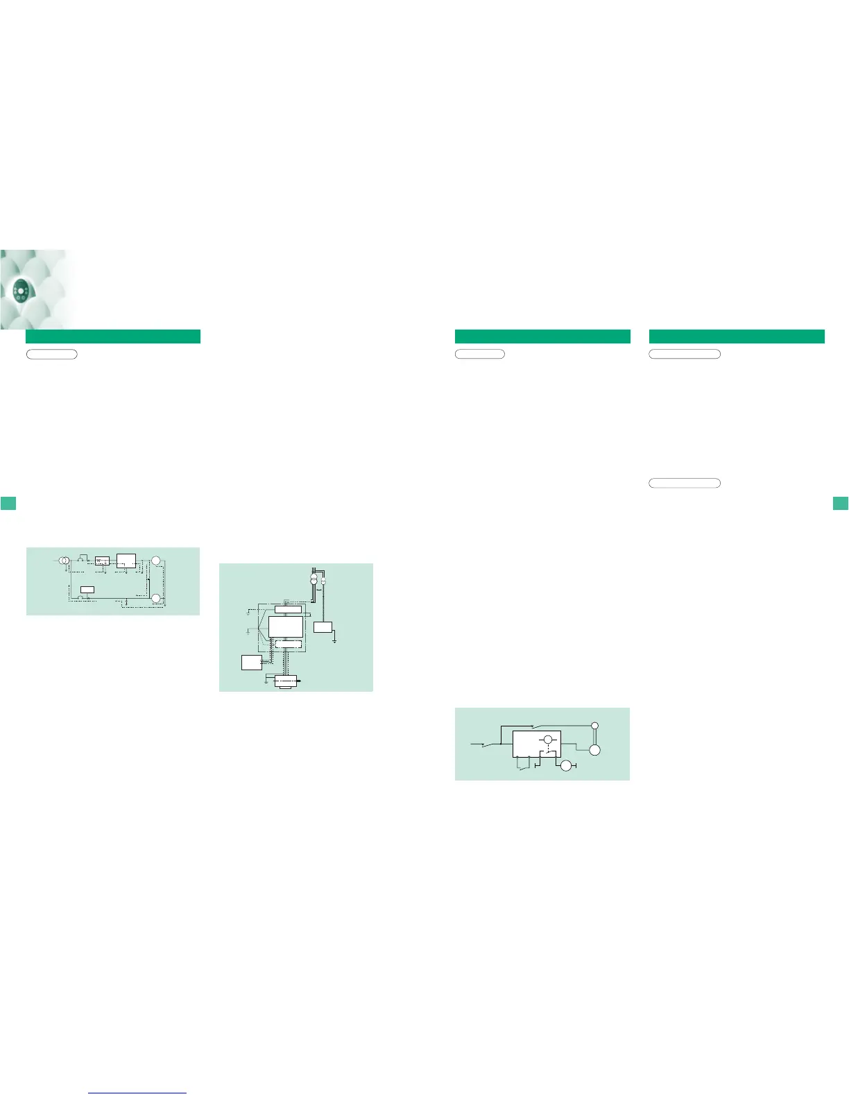
Leakage current flow routes
For inverter users
For inverter users
Notes
When studying how to use our inverters
When wiring the inverter When changing the motor speed
Wiring precautions
Application to standard motors
Installing a molded-case circuit breaker [MCCB]
(1) Install a molded-case circuit breaker (MCCB) on the inverter's power supply
input to protect the wiring.
(2) Avoid turning the molded-case circuit breaker on and off frequently to turn on/off
the motor.
(3) To turn on/off the motor frequently, close/break the control terminals F (or R)-
CC.
Installing a magnetic contactor [MC] [primary side]
(1) To prevent an automatic restart after the power interruption or overload relay has
tripped, or actuation of the protective circuit, install an electro-magnetic contact in
the power supply.
(2) The inverter is provided with a failure detection relay (FL), so that, if its contacts
are connected to the operation circuit of the magnetic contactor on the primary
side, the magnetic contactor will be opened when the protective circuit of the
inverter is activated.
(3) The inverter can be used without a magnetic contactor. In this case, use an
MCCB (equipped with a voltage tripping device) for opening the primary circuit
when the inverter protective circuit is activated.
(4) Avoid turning the magnetic contactor on and off frequently to turn on/off the
motor.
(5) To turn on/off the motor frequently, close/break the control terminals F (or R)-
CC.
Installing a magnetic contactor [MC] [secondary side]
(1) As a rule, if a magnetic contactor is installed between the inverter and the motor,
do not turn ON/OFF while running. (If the secondary-side contactor is turned
ON/OFF while running, a large current may flow in the inverter, causing inverter
damage and failure.)
(2) A magnetic contactor may be installed to change the motor or change to the
commercial power source when the inverter is stopped. Always use an interlock
with the magnetic contactor in this situation so that the commercial power supply is
not applied to the inverter's output terminals.
External signal
(1) Use a relay rated for low currents. Mount a surge suppressor on the excitation
coil of the relay.
(2) When wiring the control circuit, use shielded wires or twisted pair cables.
(3) All control terminals, except FLA, FLB and FLC are electronic circuits.
Therefore, input signal must insulate with power circuit.
Installing an overload relay
(1) The VF-S11 inverter has an electronic-thermal overload protective function.
However, in the following cases, the thermal relay operation level must be adjusted
or an overload relay matching the motor's characteristics must be installed
between the inverter and the motor.
(a) When using a motor having a rated current value different from that of the
equivalent.
(b) When driving several motors simultaneously.
(2) When using the inverter to control the operation of a constant-torque motor (VF
motor), change the protective characteristic of the electronic thermal relay
according to the setting of the VF motor.
(3) In order to adequately protect a motor used for low-speed operation, we
recommend the use of a motor equipped with a embedded thermal relay.
Vibration
When a motor is operated with an industrial inverter, it experiences more vibrations
than when it is operated by the commercial power supply. The vibration can be
reduced to a negligible level by securing the motor and machine to the base firmly.
If the base is weak, however, the vibration may increase at a light load due to
resonance with the mechanical system.
Reduction gear, belt, chain
Note that the lubrication capability of a reducer or a converter used as the interface
of the motor and the load machine may affected at low speeds.
When operating at a frequencies exceeding 60 Hz or higher, power transmission
mechanisms such as reduction gear, belts and chains, may cause problems such as
production of noise, a reduction in strength, or shortening of service life.
Frequency
Before setting the maximum frequency to 60 Hz or higher, confirm that this
operating range is acceptable for the motor.
Application to special motors
Braking motor
When using a braking motor, if the braking circuit is directly connected to the
inverters's output terminals, the brake cannot be released because of the lowered
starting voltage. Therefore, when using a braking motor, connect the braking circuit
to the inverter's power supply side, as shown on the left. Usually, braking motors
produce larger noise in low speed ranges.
Note: In the case of the circuit shown on the left, assign the function of detecting low-
speed signals to the RY and RC terminals. Make sure the parameter F130 is
set to 4 (factory default setting).
Gear motor
When using an industrial inverter to drive a gear motor, inquire of the motor
manufacturer about its continuous operation range, since low-speed operation of a
gear motor may cause insufficient lubrication.
Toshiba Gold Motor (High-efficiency power-saving motor)
Inverter-driven operation of Toshiba Gold Motors is the best solution for saving
energy. This is because these motors have improved efficiency, power factor, and
noise/vibration reduction characteristics when compared to standard motors.
Pole-changing motor
Pole-changing motors can be driven by this inverter. Before changing poles,
however, be sure to let the motor come to a complete stop.
Hight-pole-count motors
Note that hight-pole count motors(8 or more poles), which may be used for fans,etc.,
have higher rated current than 4-pole moters.
The current ratings of multipole motors are relatively high. So, when selecting an
inverter, you must pay special attention to its current rating so that the current rating
of the motor is below that of the inverter.
Single-phase motor
Because single-phase motors are equipped with a centrifugal switch and capacitors
for starting, they cannot be driven by an inverter. If only a single-phase, power
system is availabls a 3-phase motor can be driven by using a single-phase input
interter to convert it into a 3-phase 240V output. (A special inverter and a 3-phase
motor are required.)
MC1
MC2
F
B
CC
RY RC
IM
Power
supply
Run/stop
Non-excitation activation
type brake
( )
MC2
RY
Leakage current
This inverter uses high-speed switching devices for PWM control.
When a relatively long cable is used for power supply to an inverter, current may leak
from the cable or the motor to the ground because of its capacitance, adversely
affecting peripheral equipment. The intensity of such a leakage current depends on
the PWM carrier frequency, the lengths of the input and output cables, etc., of the
inverter. To prevent current leakage, it is recommended to take the following
measures.
【Effects of leakage current】
Leakage current which increases when an inverter is used may pass through the
following routes:
Route (1) ...
Leakage due to the capacitance between the ground and the noise filter
Route (2) ... Leakage due to the capacitance between the ground and the inverter
Route (3) ...
Leakage due to the capacitance between ground and the cable connecting
the inverter and the motor
Route (4) ...
Leakage due to the capacitance of the cable connecting the motor and an inverter in
another power distribution line
Route (5) ... Leakage through the grounding line common to motors
Route (6) ... Leakage to another line because of the capacitance of the ground
Leakage current which passes through the above routes may cause the following
trouble.
●Malfunction of a leakage circuit breaker in the same or another power
distribution line
●Malfunction of a ground-relay installed in the same or another power distribution
line
●Noise produced at the output of an electronic device in another power
distribution line
●Activation of an external thermal relay installed between the inverter and the
motor, at a current below the rate current
(3) Ground (shield) the main circuit wires with metallic conduits.
(4) Use the shortest possible cables to connect the inverter to the motor.
(5) If the inverter has a high-attenuation EMI filter, turn off the grounding capacitor
detachment switch to reduce the leakage current. Note that doing so leads to a
reduction in the noise attenuating effect.
Note) This inverter allows you to decrease the frequency up to 2.0kHz.
I
f the carrier frequency reduce, the acoustic noise caused by the motor increase.
Ground fault
Before begining operation, thoroughly check the wiring between the motor and the
inverter for incorrect wiring or short circuits. Do not ground the neutral
point of any star-connected motor.
Radio interference
[Noise produced by inverters]
Since this inverter performs PWM control, it produces noise and sometimes affects
nearby instrumental devices, electrical and electronic systems, etc. The effects of
noise greatly vary with the noise resistance of each individual device, its wiring
condition, the distance between it and the inverter, etc.
[
Measures against noises
]
According to the route through which noise is transmitted, the noises produced by an
inverter are classified into transmission noise, induction noise and radiation noise.
[
Examples of protective measures
]
●
Separate the power line from other lines, such as weak-current lines and signal
lines, and install them apart from each other.
●Install a noise filter in each inverter. It is effective for noise prevention to install
noise filters in other devices and systems, as well.
●Shield cables and wires with grounded metallic conduits, and cover electronic
systems with grounded metallic cases.
●Separate the power distribution line of the inverter from that of other devices and
systems.
●Install the input and output cables of the inverter apart from each other.
●Use shielded twisted pair wires for wiring of the weak-current and signal circuits,
and always ground one of each pair of wires.
●Ground the inverter with grounding wires as large and short as possible,
separately from other devices and systems.
The single-phase 240V and three-phase 500V models have built-in noise
filters which significantly reduce noise.
Power factor improvement capacitors
Do not install a power factor improvement capacitors on the input or output side of
the inverter.
Installing a power factor improvement capacitor on the input or output side causes
current containing harmonic components to flow into the capacitor, adversely
affecting the capacitor itself or causing the inverter to trip. To improve the power
factor, install an input AC reactor or a DC reactor (optional) on the primary side of
the inverter.
Installation of input AC reactors
These devices are used to improve the input power factor and suppress high
harmonic currents and surges. Install an input AC reactor when using this inverter
under the following conditions:
(1) When the power source capacity is 200kVA or more, and when it is 10 times
or more greater than the inverter capacity.
(2) When the inverter is connected the same power distribution system as a
thyristor-committed control equipment.
(3) When the inverter is connected to the same power distribution system as that
of distorted wave-producing systems, such as arc furnaces and large-capacity
inverters.
【Measures against effects of leakage current】
The measures against the effects of leakage current are as follows:
1) Measures to prevent the malfunction of leakage circuit breakers
(1) Decrease the PWM carrier frequency of the inverter.
Note)
(2) Use radio-frequency interference-proof ELCBs as ground-fault interrupters in
not only the system into which the inverter is incorporated but also other
systems. When ELCBs are used, the PWM carrier frequency needs to be
increased to operate the inverter.
(3) When connecting multiple inverters to a single ELCB, use an ELCB with a
high current sensitivity or reduce the number of inverters connected to the
ELCB.
2) Measures against malfunction of ground-fault relay:
(1) Decrease the PWM carrier frequency of the inverter.
Note)
(2) Install ground-fault relays with a high-frequency protective function (e.g.,
Toshiba CCR12 type of relays) in both the same and other lines. When ELCBs
are used, the PWM carrier frequency needs to be increased to operate the
inverter.
3) Measures against noise produced by other electric and electronic systems:
(1) Separate the grounding line of the inverter from that of the affected electric
and electronic systems.
(2) Decrease the PWM carrier frequency of the inverter.
Note)
4) Measures against malfunction of external thermal relays:
(1) Remove the external thermal relay and use the electronic thermal function of
the inverter instead of it. (Unapplicable to cases where a single inverter is used
to drive more than one motor. Refer to the instruction manual for measures to
be taken when thermal relays cannot be removed.)
(2) Decrease the PWM carrier frequency of the inverter.
Note)
5) Measures by means of wiring and grounding
(1) Use a grounding wire as large as possible.
(2)
Separate the inverter's grounding wire from that of other systems or install
the
grounding wire of each system separately to the grounding point.
For inverter users
14
13
Separate grounding
Erectronic
equipment
Control panel frame
Metal conduit tube,
shielding cable,
1 point
grounding
Sensor signal
Control signal
Noise Filter
Inverter
Ground
separately as
required
Separate by 30 cm or
more. When enclosing
signal cables and power
cables in the same duct,
separate them with a
metal plate.
Twist the signal cables.
Motor
Noise Filter

 Loading...


