5 6
Standard specifications
■Common specification
Sinusoidal PWM control
Digital setting: within ±0.01% of the max. frequency (-10 to +60°C)
Analog setting: within ±0.5% of the max. frequency (25°C ±10°C)
Potentiometer on the front panel, external frequency potentiometer (connectable to a potentiometer with a rated impedance
of 1 - 10kΩ), 0 - 10Vdc (input impedance: VIA/VIB=30kΩ), 4 - 20mAdc (Input impedance: 250Ω).
The characteristic can be set arbitrarily by two-point setting. Possible to set individually for three functions: analog input (VIA and VIB) and communication command.
Three frequencies can be set. Setting of the jump frequency and the range.
Upper-limit frequency: 0 to maximum frequency, lower-limit frequency: 0 to upper-limit frequency
Adjustable within a range of 2.0 to 16.0Hz (default: 12kHz).
Setting of proportional gain, integral gain, differential gain and control wait time. Checking whether the amount of processing amount and the amount of feedback agree.
The RUN and STOP keys on the operation panel are used to start and stop operation. The switching between forward run and
reverse run can be done from one of the three control units: operation panel, terminal board and external control unit.
In the event of a momentary power failure, the inverter reads the rotational speed of the coasting motor and outputs a frequency appropriate
to the rotational speed in order to restart the motor smoothly. This function can also be used when switching to commercial power.
Switching between standard motor and constant-torque VF motor, switching between motors 1 and 2, setting of overload
trip time, adjustment of stall prevention levels 1 and 2, selection of overload stall
Stores data on the past four trips: number of trips that occurred in succession, operation frequency, direction of rotation, load current, input
voltage, output voltage, information on input terminals, information on output terminals, and cumulative operation time when each trip occurred.
Lamps indicating the inverter status by lighting, such as RUN lamp, MON lamp, PRG lamp, % lamp, Hz lamp, frequency
setting potentiometer lamp, UP/DOWN key lamp and RUN key lamp. The charge lamp indicates that the main circuit
capacitors are electrically charged.
Function of resetting by closing contact 1a or by turning off power or the operation panel. This function is also used to save and clear trip records.
Stall prevention, overvoltage, overload, under-voltage, setting error, retry in process, upper/lower limits
Indoor, altitude: 1000m (Max.), not exposed to direct sunlight, corrosive gas, explosive gas / vibration (less than 5.9m/s
2
) (10 to 55Hz)
-10 to +60°C
Note 9,10)
-25 to +70°C
20 to 93% (free from condensation and vapor).
Stall prevention, current limitation, over-current, output short circuit, over-voltage, over-voltage limitation, undervoltage, ground fault, power supply phase
failure, output phase failure, overload protection by electronic thermal function, armature over-current at start-up, load side over-current at start-up, over-
torque, undercurrent, overheating, cumulative operation time, life alarm, emergency stop, braking resistor over-current/overload, various pre-alarms
Over-current, overvoltage, overheating, short-circuit in load, ground fault, overload on inverter, over-current through arm at start-up, over-
current through load at start-up, CPU fault, EEPROM fault, RAM fault, ROM fault, communication error. (Selectable: Over-current
through braking resistor/overload, emergency stop, under-voltage, low voltage, over-torque, motor overload, output open-phase)
Analog output (1mAdc full-scale DC ammeter or 7.5Vdc full-scale DC voltmeter/rectifier type AC voltmeter, 4 to 20mA/0
to 20mA output)
Operation frequency, operation frequency command, forward/reverse run, output current, voltage in DC section, output voltage, torque,
torque current, load factor of inverter, integral load factor of PBR, input power, output power, information on input terminals, information on
output terminals, version of CPU1, version of CPU2, version of memory, PID feedback amount, frequency command (after PID), integral
input power, integral output power, rated current, causes of past trips 1 through 4, information on life alarm, cumulative operation time
Frequency: inverter output frequency.
Alarm: stall alarm “C”, overvoltage alarm “P”, overload alarm “L”, overheat alarm “H”.
Status: inverter status (frequency, cause of activation of protective function, input/output voltage, output current, etc.) and parameter settings.
Free-unit display: arbitrary unit (e.g. rotating speed) corresponding to output frequency.
Possible to select from 76 functions, such as forward/reverse run signal input, jog run signal input, operation base signal
input and reset signal input, to assign to 8 input terminals. Logic selectable between sink and source.
Possible to select from 58 functions, such as upper/lower limit frequency signal output, low speed detection signal output, specified speed
reach signal output and failure signal output, to assign to FL relay output, open collector output and RY output terminals.
Capable of restarting automatically after a check of the main circuit elements in case the protective function is activated. 10 times (Max.) (selectable with a parameter)
Possible to write-protect parameters and to prohibit the change of panel frequency settings and the use of operation panel for operation, emergency stop or resetting.
Possible to keep the motor running using its regenerative energy in case of a momentary power failure.
When two or more inverters are used to operate a single load, this function prevents load from concentrating on one inverter due to unbalance.
The sum of two analog signals (VIA/VIB) can be used as a frequency command value.
1c-contact output: (250Vac-0.5A-cos
φ
=
0.4)
Braking start-up frequency: 0 to maximum frequency, braking rate: 0 to 100%, braking time: 0 to 20 seconds, emergency
DC braking, motor shaft fixing control
Selectable from among acceleration/deceleration times 1, 2 or 3 (0.0 to 3200 sec.). Automatic acceleration/deceleration function.
S-pattern 1 or 2, and S-pattern value adjustable. Forced rapid deceleration and dynamic rapid deceleration function.
Control and drive circuit is built in the inverter with the braking resistor outside (optional).
Jog mode, if selected, allows jog operation from the operation panel or the terminal board.
Base frequency + 15-speed operation possible by changing the combination of 4 contacts on the terminal board.
Adjustable within the range of 50 to 600V by correcting the supply voltage (not adjustable above the input voltage)
0.5 to 500.0Hz, default setting: 0.5 to 80Hz, maximum frequency: 30 to 500Hz
0.01Hz: operation panel setting, 0.1Hz: analog input (when the max. frequency is 100Hz).
V/f constant, variable torque, automatic torque boost, vector control, automatic energy-saving, dynamic automatic energy-
saving control. Auto-tuning. Base frequency (25 - 500Hz) adjusting to 1 or 2, torque boost (0 - 30%) adjusting to 1 or 2,
adjusting frequency at start (0.5 - 10Hz)
Principal control functionsOperation specificationsProtective functionDisplay function
Environments
Control system
Rated output voltage
Output frequency range
Minimum setting steps of frequency
Frequency accuracy
Voltage/frequency characteristics
Frequency setting signal
Terminal board base frequency
Frequency jump
Upper- and lower-limit frequencies
PWM carrier frequency
PID control
Acceleration/deceleration time
DC braking
Dynamic braking
Input terminal function
(programmable)
Output terminal functions
(programmable)
Forward/reverse run
Jog run
Preset speed operation
Retry operation
Various prohibition settings
Regenerative power ride-through control
Auto-restart operation
Drooping function
Override function
Failure detection signal
Protective function
Electronic thermal characteristic
Reset function
Alarms
Causes of failures
Monitoring function
Past trip monitoring function
Output for frequency meter
4-digit 7-segments LED
Indicator
Use environments
Ambient temperature
Storage temperature
Relative humidity
SpecificationItem
■3-phase 240V
■1-phase 240V ■3-phase 600V
Item Specification
3-phase 240V
VFS11
3-phase 200V to 240V
150%-60 seconds, 200%-0.5 second
Note 4)
3-phase 200V to 240V - 50/60Hz
Voltage + 10%, -15%
Note 5)
, frequency ±5%
IP20 Enclosed type (JEM1030)
Munsel 5Y-8/0.5
Self-cooling
Basic filter
Note 7)
Forced air-cooled
3.3
(3.3)
4.8
(4.4)
8.0
(7.9)
17.5
(16.4)
27.5
(25.0)
33
(33)
54
(49)
66
(60)
2004PM
1.3
2007PM
1.8
2015PM
3.0
2037PM
6.7
2055PM
10
2075PM
13
2110PM
21
2150PM
25
0.4
3.7
(3.3)
2005PM
1.4
0.55 0.75 1.5
11.0
(10.0)
2022PM
4.2
2.2 4.0 5.5 7.5 11 15
Input voltage class
Applicable motor (kW)
Protective method
Cooling method
Color
Built-in filter
Type
Form
Capacity (kVA)
Note 1)
Output voltage
Note 3)
Overload current rating
Voltage-frequency
Allowable fluctuation
Rated output current
(A)
Note 2)
Rating
Power
supply
Item
Note 1.
Note 2.
Note 3.
Note 4.
Note 5.
Note 6.
Note 7.
Note 8.
Note 9.
Note
10
.
Capacity is calculated at 220V for the 240V class, at 440V for the 500V class and at 575V for the 600V models.
Indicates rated output current setting when the PWM carrier frequency (parameter F300) is 4kHz or less.
When exceeding 4kHz, the rated output current setting is indicated in the parenthesis. When the input power voltage of the 500V class model exceeds 480V, it is necessary to further reduce the setting. The default
setting of the PWM carrier Frequency is 12kHz.
Maximum output voltage is the same as the input voltage.
May differ according to voltage and model.
±10% when the inverter is used continuously (load of 100%).
If you are using 600V model, be sure to connect an input reactor (ACL).
Built-in standard filter: Core and capacities With RFI noise filter option: Complies EN55011 Class A Group 1(Max.5m*) and Class B Group 1(Max.1m*)
* Length of motor connecting cable.
Built-in high-attenuation EMI filter: Complies EN55011 Class A Group 1(Max.5m*) With RFI noise filter option : Complies EN55011 Class B Group 1(Max.20m*) and Class A Group 1(Max.50m*)
* Length of motor connecting cable.
Above 40°C : Remove the protective seal from the top of the inverter. Above 50°C: Remove the seal from the top of the inverter and use the inverter with the rated output current reduced.
If inverters are installed side by side (with no sufficient space left between them) installation: Remove the seal from the top of each inverter.
When installing the inverter where the ambient temperature will rise above 40°C, remove the seal from the top of the inverter and use the inverter with the rated output current reduced.
■3-phase 500V
Item
Standard specifications
Input voltage class
Applicable motor (kW)
Protective method
Cooling method
Color
Built-in filter
Type
Form
Capacity (kVA)
Note 1)
Output voltage
Note 3)
Overload current rating
Voltage-frequency
Allowable fluctuation
Rated output current
(A)
Note 2)
Rating
Power
supply
Input voltage class
Applicable motor (kW)
Protective method
Cooling method
Color
Built-in filter
Type
Form
Capacity (kVA)
Note 1)
Output voltage
Note 3)
Overload current rating
Voltage-frequency
Allowable fluctuation
Rated output current
(A)
Note 2)
Rating
Power
supply
IP20 Enclosed type (JEM1030)
3-phase 500V
3-phase 380V to 500V
150%-60 seconds, 200% -0.5 second
Note 4)
3-phase 380V to 500V - 50/60Hz
Voltage + 10%, -15%
Note 5)
, frequency ±5%
0.75 1.5 2.2 4.0 5.5 7.5 11 15
4007PL
1.8
2.3
(2.1)
0.4
4004PL
1.1
1.5
(1.5)
4015PL
3.1
4.1
(3.7)
4022PL
4.2
5.5
(5.0)
4037PL
7.2
4055PL
11
4075PL
13
4110PL
21
4150PL
25
9.5
(8.6)
14.3
(13.0)
17.0
(17.0)
27.7
(25.0)
33
(30)
Forced air-cooled
Munsel 5Y-8/0.5
High-attenuation EMI filter
Note 8)
Specification
VFS11
1-phase 240V 3-phase 600V
Note 6)
VFS11S VFS11
3-phase 200V to 240V
1-phase 200V to 240V – 50/60Hz 3-phase 525V to 600V – 50/60Hz
3-phase 525V to 600V
0.2 0.4 0.75 1.5 2.2
2002PL
0.6
1.5
(1.5)
2004PL
1.3
3.3
(3.3)
2007PL
1.8
4.8
(4.4)
2015PL
3.0
8.0
(7.9)
2022PL
4.2
11.0
(10.0)
0.75
6007P
1.7
1.7
(1.5)
1.5
6015P
2.7
2.7
(2.4)
2.2
6022P
3.9
3.9
(3.5)
4.0
6037P
6.1
6.1
(5.5)
5.5
6055P
9.0
9.0
(8.1)
7.5
6075P
11
11.0
(9.9)
11
6110P
17
17.0
(15.3)
15
6150P
22
22.0
(19.8)
Self-cooling
Forced air-cooled Forced air-cooled
IP20 Enclosed type (JEM1030)
150%-60 seconds, 200%-0.5 second
Note 4)
Voltage + 10%, -15%
Note 5)
, frequency±5%
Munsel 5Y-8/0.5
IP20 Enclosed type (JEM1030)
150%-60 seconds, 200%-0.5 second
Note 4)
Voltage + 10%, -15%
Note 5)
, frequency±5%
Munsel 5Y-8/0.5
High-attenuation EMI filter
Note 8)
No filter
Specification
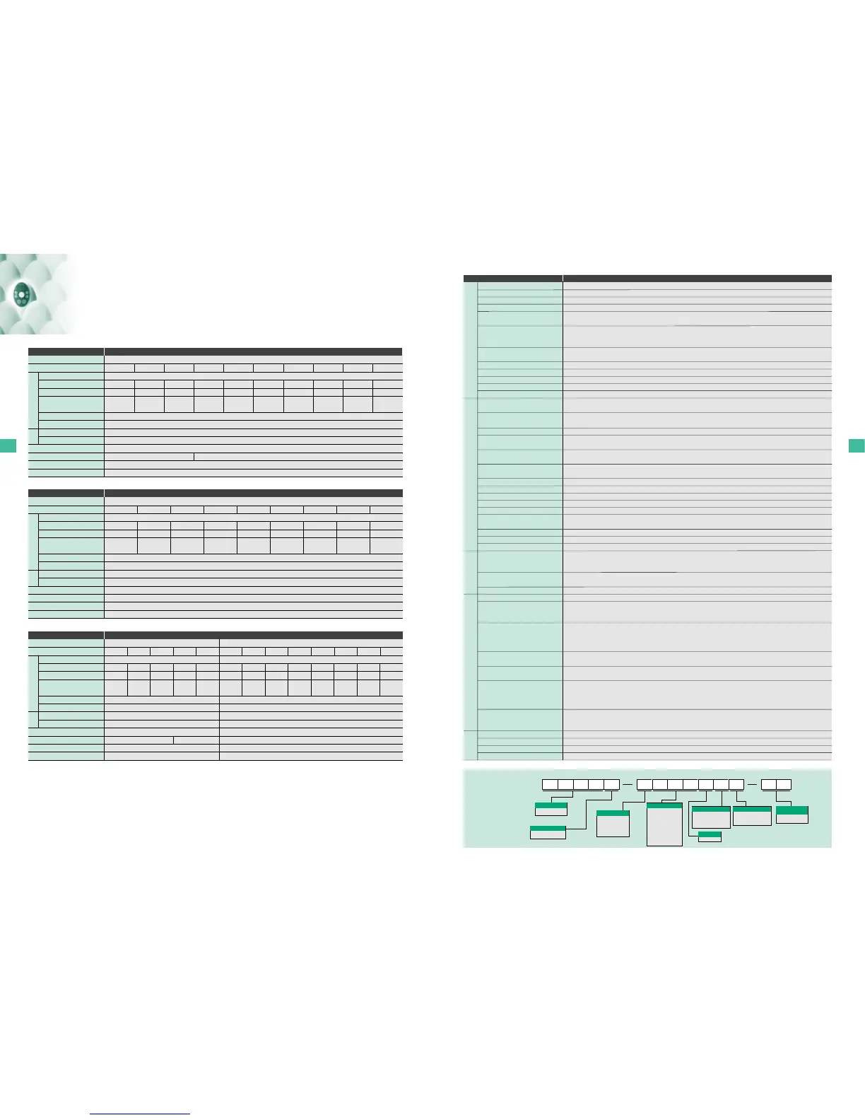
Type Form
SVF 11S 2007PLE WN
TOSVERT
VF-S11 Series
S: 1-phase
None: 3-phase
2: 240V class
(200 to 240V)
4: 500V class
(380V to 500V)
6: 600V class
(525V to 600V)
None: No filter
L: High-attenuation EMI
filter inside
M: Basic filter inside
WN: Sink(Negative)
WP: Source(Positive)
P: Provided
Note) Interface logic can be
switched by slide switch easily.
002: 0.2kW
004: 0.4kW
005: 0.55kW
007: 0.75kW
015: 1.5kW
022: 2.2kW
037: 4.0kW
055: 5.5kW
075: 7.5kW
110: 11kW
150: 15kW
Model name
Number of power phases
Input voltage
Applicable motor capacity
Additional functionsⅠ
None: Standard type
E: Totally enclosed type
U: Open type
Additional functionsⅡ
Interface logic
(Shipment setting)
Operation panel
Contents of the product code
Standard specifications

 Loading...


