7 8
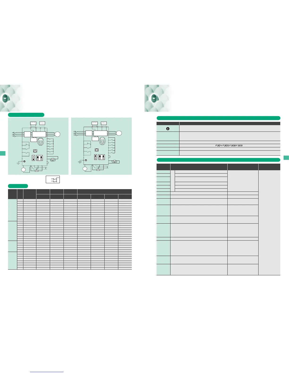
wiring devices
Main circuit power supply
240V class: three-phase 200-240V -50/60Hz
500V class: three-phase 380-500V -50/60Hz
600V class: three-phase 525-600V -50/60Hz
*1
R/L1
S/L2
T/L3
U/T1
V/T2
W/T3
I M
FLC
FLB
FLA
RY
PLC
RC
Motor
F
R
RES
S1
S2
S3
CC
P24
OUT
NO
CC
FM
PLC
CC
VIA
VIB
PP
+
+
−
−
P0
PA/+
PB PC/-
Meter
Voltage signal: 0-10V
(Current signal: 4-20mA)
Voltage signal: 0-10V
(Current signal: 4-20mA)
External potentiometer (1-10kΩ)
(or input voltage signal across VIB-CC terminals: 0-10V)
External potentiometer (1-10kΩ)
(or input voltage signal across VIB-CC terminals: 0-10V)
Control
circuit
Operation
panel
Fault detection relay
Fault detection relay
Ry
VF-S11
Frequency
meter
(ammeter)
Main circuit
Noise
filter
DC reactor (DCL)
*2 (option)
Connector for
common serial
communications
Operation
panel
Connector for
common serial
communications
Foward
Reverse
Reset
Preset-speed 1
Preset-speed 2
Preset-speed 3
Foward
Reverse
Reset
Preset-speed 1
Preset-speed 2
Preset-speed 3
Common
Braking resistor (option)
DC reactor (DCL)
*2 (option)
Braking resistor (option)
Sink (Negative) logic : common
=
CC
Low-speed
signal output
External 24Vdc
power input
Low-speed
signal output
External 24Vdc
power input
MCCB(2P)
R/L1
S/L2
Power supply
1ø 200~240V
-50/60HZ
Speed reach
signal output
Speed reach
signal output
IISINK
SW1
SOURCE
FM
V
VIA
V
*1: The T/L3 terminal not provided for signal-phase models. Use the R/L1 and S/L2 terminal as input terminals.
*2: The inverter came with the PO and the PA/+ terminals shorted by means of a shoeting bar.
Before installing the DC reactor (DCL), remove the bar.
*3: When using the OUT output terminal in sink logic mode, short-circuit the NO and CC terminals.
*4: When using the NO output terminal in source logic mode, short-circuit the P24 and OUT terminals.
*3
*4
MCCB
MCCB
*1
R/L1
S/L2
T/L3
U/T1
V/T2
W/T3
FLC
FLB
FLA
RY
RC
P24
F
R
RES
S1
S2
S3
P24
OUT
NO
CC
+
+
−
−
P0
VF-S11
Source (Positive) logic : common
=
P24
FM
CC
VIA
VIB
PP
PLC
PA/+
PB PC/-
IISINK
SW1
SOURCE
FM
V
VIA
V
Ry
Connection diagram and selection of wiring devices
Note) 1. Be sure to attach surge killer to the exciting coil of the relay and the magnetic contactor.
2. 500V and 600V class: For the operation and control circuit, regulate the voltage at 240V or less with a step-down transformer.
3. When using the auxiliary contacts 2a of the magnetic contactor MC for the control circuit, connect the contacts 2a in parallel to increase reliability.
4. Size of the wires conected to the input terminals R, S and T and the output terminals U, V and W when the length of each wire does not exceed 30m.
5. For the control circuit, use shielded wires 0.75 mm
2
or more in diameter.
6. For grounding, use a cable with a size equal to or larger than the above.
7. The wire sizes specified in the above table apply to HIV wires (cupper wires shielded with an insulator with a maximum allowable temperature of 75°C) used at an ambient temperature of 50°C or less.
8. The numeric values in parentheses refer to the sizes of wires to be used when a DC reactor is connected.
I M
Motor
Meter
Frequency
meter
(ammeter)
Noise
filter
Main circuit
Control
circuit
3-phase
240V class
3-phase
500V class
Voltage
class
Interver model
Rated current(A)
Note 8)
Rated current(A)
Note 8)
Adjusted current
(A) (For reference)
Main circuit
(mm
2
) Note 4,8)
DC reactor
(optional)(mm
2
)
Braking resistor
(optional)(mm
2
)
Grounding cable
(mm
2
)Note 6)
Molded-case circuit breaker (MCCB)
Earth leakage circuite breaker(ELCB)
Magnetic contactor
(MC)
Wire size (mm
2
)
Overload relay
(Th-Ry)
Capacity
applicable
motor
(kW)
1-phase
240V class
3-phase
600V class
Main circuit teminal functions
Control circuit terminal functions
Grounding terminal for connecting inverter. There are 3 terminals in total. 2 terminals in the terminal board, 1 terminal in the cooling fin.
Connect to a (three-phase induction) motor.
240V class: single-phase 200~240V-50/60Hz
three-phase 200~240V-50/60Hz
500V class: three-phase 380~500V-50/60Hz
600V class: three-phase 525~600V-50/60Hz
Connect to braking resistors. Change parameters , , , if necessary.
This is a negative potential terminal in the internal DC main circuit. DC common power can be input across the PA/+ terminals (positive potential).
Terminals for connecting a DC reactor (DCL: optional external device). Shorted by a short bar when shipped from the factory. Before
installing DCL, remove the short bar.
R/L1, S/L2, T/L3
U/T1, V/T2, W/T3
PA/+, PB
PC/−
PO, PA/+
* Single-phase input: R/L1 and S/L2 terminals
Terminals symbol Terminal function
*Sink/Source/
PLC selectable using SW
Multifunction programmable
contact input
Shorting across RES-CC causes a held reset when the inverter protector function is operating. Note
that when the inverter is operating normally, it will not operate even if there is a short across RES-CC.
F
Dry contact input
24Vdc - 5mA or less
R
Shorting across F-CC causes forward rotation; open causes slowdown and stop.
Shorting across R-CC causes reverce rotation; open causes slowdown and stop.
RES
S1
S2
S3
Shorting across S1-CC causes preset speed operation.
Shorting across S2-CC causes preset speed operation.
Shorting across S3-CC causes preset speed operation.
CC
PLC
Control circuit’s equipotential terminal (sink logic).3 common terminals for input/output.
PP
10Vdc
(permissible load current: 10mAdc)
(Insulation resistance: 50Vdc)
Power output for analog input setting.
Multifunction programmable analog input. Standard default setting: 0-10Vdc
input and 0-60Hz frequency. The function can be changed to 4-20 mAdc (0-
20 mA) current input by flipping the VIA slide switch to the I position.
Multifunction programmable analog input. Standard default setting: 0-10Vdc
input and 0-50Hz (50Hz setting) or 0-60Hz (60Hz setting) frequency.
External 24Vdc power input
When the source logic is used, a common terminal 24Vdc is connected.
VIA
Note 1)
Note 2)
Note 1)
Note 2)
10Vdc
(internal impedance: 30kΩ)
4~20mA
(Internal impedance: 250Ω)
Pulse train output
10mA or more
Multifunction programmable relay contact output.
Contact ratings: 250Vac - 2A (cosø = 1), 30Vdc - 1A, 250Vac - 1A (cosø = 0.4).
Standard default settings detect and output low-speed signal output frequencies.
Multifunction programmable open collector output. Standard default settings
detect and output speed reach signal output frequencies.
The NO terminal is an isoelectric output terminal. It is insulated from the CC
terminal.
These terminals can also be used as multifunction programmable pulse train
output terminals.
Multifunction programmable analog output.
Standard default setting: output freguency. Connect a 1mAdc full-scale
ammeter or 7.5Vdc (10Vdc)-1mA full-scale voltmeter.
The function can be changed to 0-20mAdc (4-20mA) current output by
flipping the FM slide switch to the I position.
VIB
10Vdc
(internal impedance: 30kΩ)
FM
1mA full-scale DC ammeter
or 7.5Vdc 1mA full-scale
DC voltmeter
0-20mA (4-20mA) full-scale
DC ammeter
P24
24Vdc - 100mA
OUT
NO
Multifunction programmable relay contact output.
Contact ratings: 250Vac-1A (cosø = 1), 30Vdc-0.5A, 250Vac-0.5A (cosø = 0.4).
Detects the opertion of the inverter’s protection function. Contact across FLA-FLC is
closed and FLB-FLC is opened during protection function operation.
RC
RY
FLA
FLB
FLC
Open collector output:
24Vdc - 50mA
250Vac - 1A: at resistance load
30Vdc - 0.5A, 250Vac - 0.5A
(cosø = 0.4)
250Vac - 1A: at resistance load
30Vdc - 0.5A, 250Vac - 0.5A
(cosø = 0.4)
Terminal
symbol
Function Electrical specifications Wire size
Screwdriver:
Small-sized flat-blade screwdriver
Blade thickness:
0.4 mm or less
Blade width: 2.5 mm or less
Note 1: By changing parameter setting, this terminal can also be used as a multifunction programmable contact input terminal.
When the inverter is used in a sink logic configuration, a resistor (4.7kΩ at 0.5W) should be inserted between the P24 and VIA/VIB terminals.
Also, the slide switch for the VIA terminal needs to be turned to the V position.
Note 2: Multifunction output terminals to which two different functions can be assigned.
Terminal functions
Solid wire : 0.3 to 1.5 (mm
2
)
Stranded wire :
0.3 to 1.5 (mm
2
)
(AWG22 to 16)
Sheath strip length : 6 (mm)
Terminal functions
Connection diagram and selection of wiring devices
PLC
0.4
0.55
0.75
1.5
2.2
4.0
5.5
7.5
11
15
0.4
0.75
1.5
2.2
4.0
5.5
7.5
11
15
0.2
0.4
0.75
1.5
2.2
0.75
1.5
2.2
4.0
5.5
7.5
11
15
VFS11-2004PM
VFS11-2005PM
VFS11-2007PM
VFS11-2015PM
VFS11-2022PM
VFS11-2037PM
VFS11-2055PM
VFS11-2075PM
VFS11-2110PM
VFS11-2150PM
VFS11-4004PL
VFS11-4007PL
VFS11-4015PL
VFS11-4022PL
VFS11-4037PL
VFS11-4055PL
VFS11-4075PL
VFS11-4110PL
VFS11-4150PL
VFS11S-2002PL
VFS11S-2004PL
VFS11S-2007PL
VFS11S-2015PL
VFS11S-2022PL
VFS11-6007P
VFS11-6015P
VFS11-6022P
VFS11-6037P
VFS11-6055P
VFS11-6075P
VFS11-6110P
VFS11-6150P
5(5)
10(5)
10(5)
15(10)
20(15)
30(30)
50(40)
60(50)
100(75)
125(100)
5(5)
5(5)
10(10)
15(10)
20(15)
30(20)
30(30)
50(40)
60(50)
5(5)
10(5)
15(10)
20(15)
30(30)
5(5)
10(10)
10(10)
15(15)
20(20)
30(30)
30(30)
40(40)
9(9)
9(9)
9(9)
9(9)
12(12)
25(18)
32(25)
38(38)
65(50)
80(65)
9(9)
9(9)
9(9)
9(9)
12(9)
18(18)
25(18)
32(25)
38(38)
9(9)
9(9)
9(9)
18(12)
25(18)
9(9)
9(9)
9(9)
12(12)
18(18)
25(25)
25(25)
33(33)
2.3
2.7
3.6
6.8
9.3
15
22
28
44
57
1.0
1.6
3.6
5.0
6.8
11
15
22
28
1.3
2.3
3.6
6.8
9.3
1.0
1.6
3.6
5.0
6.8
11
15
22
2.0(2.0)
2.0(2.0)
2.0(2.0)
2.0(2.0)
2.0(2.0)
3.5(2.0)
5.5(2.0)
8.0(5.5)
14(8.0)
14(14)
2.0(2.0)
2.0(2.0)
2.0(2.0)
2.0(2.0)
2.0(2.0)
2.0(2.0)
3.5(2.0)
5.5(2.0)
8.0(5.5)
2.0(2.0)
2.0(2.0)
2.0(2.0)
2.0(2.0)
2.0(2.0)
2.0(2.0)
2.0(2.0)
2.0(2.0)
2.0(2.0)
2.0(2.0)
2.0(2.0)
3.5(3.5)
5.5(5.5)
1.25
2.0
2.0
2.0
2.0
2.0
3.5
5.5
8.0
14
2.0
2.0
2.0
2.0
2.0
2.0
2.0
3.5
5.5
2.0
2.0
2.0
2.0
2.0
2.0
2.0
2.0
2.0
2.0
2.0
3.5
5.5
2.0
2.0
2.0
2.0
2.0
2.0
5.5
5.5
5.5
5.5
2.0
2.0
2.0
2.0
2.0
2.0
2.0
2.0
2.0
2.0
2.0
2.0
2.0
2.0
2.0
2.0
2.0
2.0
2.0
2.0
2.0
2.0
3.5
3.5
3.5
3.5
3.5
3.5
5.5
8.0
14
14
3.5
3.5
3.5
3.5
3.5
3.5
3.5
5.5
8.0
3.5
3.5
3.5
3.5
3.5
3.5
3.5
3.5
3.5
3.5
3.5
3.5
3.5
Standard connection diagram

 Loading...


