For inverter users
Peripheral devices
For inverter users
15
16
Peripheral devices
Harmonic current and influence to power supply
Selecting the capacity (model) of the inverter
Selection
Capacity
Refer to the applicable motor capacities listed in the standard specifications.
When driving a high-pole motor, special motor, or multiple motors in parallel, select
such an inverter that the sum of the motor rated current multiplied by 1.05 to 1.1 is
less than the inverter's rated output current value.
Acceleration/deceleration times
The actual acceleration and deceleration times of a motor driven by an inverter are
determined by the torque and moment of inertia2 of the load, and can be calculated
by the following equations.
The acceleration and deceleration times of an inverter can be set individually. In any
case, however, they should be set longer than their respective values determined by
the following equations.
Allowable torque characteristics
When a standard motor is combined with an inverter to perform variable speed
operation, the motor temperature rises slightly higher than it normally does during
commercial power supply operation. This is because the inverter output voltage has
a sinusoidal (approximate) PWM waveform. In addition, the cooling becomes less
effective at low speed, so the torque must be reduced according to the frequency.
When constant-torque operation must be performed at low speeds, use a Toshiba VF
motor designed specifically for use with inverters.
Starting characteristics
When a motor is driven by an inverter, its operation is restricted by the inverter’s
overload current rating, so the starting characteristic is different from those obtained
from commercial power supply operation.
Although the starting torque is smaller with an inverter than with the commercial
power supply, a high starting torque can be produced at low speeds by adjusting the
V/f pattern torque boost amount or by employing vector control. (200% in
sensorless control mode, though this rate varies with the motor characteristics.)
When a larger starting torque is necessary, select an inverter with a larger capacity
and examine the possibility of increasing the motor capacity.
Note 1. 100% of torque refers to the amount of torque that the motor produces
when it is running at a 60Hz-synchronized speed. The starting torque is
smaller in this case than that required when power is supplied from a
commercial power line. So, the characteristics of the machine to be
operated need to be taken into consideration.
Note 2. The maximum allowable torque at 50Hz can be calculated approximately by
multiplying the maximum allowable torque at a base frequency of 60Hz by
0.8.
Acceleration time
Deceleration time
Conditions
ta= (sec.)
(JM+JL)×ΔN
9.56×(TM−TL)
ta= (sec.)
(JM+JL)×ΔN
9.56×(TB+TL)
0
0
20
40
60
80
100
120
140
160
180
200
10 20 30 40
Output frequency (Hz)
Maximum allowable continuous torque
50 60 70 80
Torque (%) (See Note 1.)
[An example of V/f
control at a base
frequency of 60 Hz]
Harmonics are defined as sinusoidal waves that is multiple freguency of commercial
power (base frequency: 50Hz or 60Hz). Commercial power including harmonics
has a distorted waveform.
Some electrical and electronic devices produce distorted waves in their rectifying
and smoothing circuits on the input side. Harmonics produced by a device influence
other electrical equipment and facilities in some cases (for example, overheating of
phase advancing capacitors and reactors).
JM
JL
△N
TL
TM
TB
: Moment of inertia of motor (kge.m
2
)
: Moment of inertia of load (kge.m
2
)
(converted into value on motor shaft)
: Difference in rotating speed between before and
after acc. or dce. (min.
-
1
)
: Load torque (Ne.m)
: Motor rated torque x 1.2-1.3 (Ne.m) ... V/f control
: Motor rated torque x 1.5 (Ne.m)
... Vector operation control
: Motor rated torque x 0.2 (Ne.m)
When a braking resistor or a braking resistor unit is used:
Motor rated torque x 0.8-1.0 (Ne.m)
()
Maximum torque
Connecting a
reactor
The leakage of a harmonic current from an inverter can be
restricted by connecting an input AC reactor (ACL) on the
input side of the inverter or a DC reactor (DCL) to the DC
section of the inverter.
1
Measures Description
No
Measures for suppressing higher harmonics
A PWM converter that shapes the waveform of an input
current into a substantially sinusoidal waveform. The leakage
of a harmonic current from a power supply can be restricted
by connecting a harmonic suppressing unit (SC7).
Connecting a
higher harmonic
suppressing
unit (SC7)
2
A harmonic current can be absorbed by the use of a phase
advancing capacitor unit composed of a phase advancing
capacitor and a DC reactor.
Connecting a higher
harmonic suppressing
phase advancing capacitor
3
For delta-delta connection and delta-Y connection
transformers, the effect of 12 pulses can be obtained by
distributing the load evenly, and thus currents containing fifth-
order and seventh-order harmonics can be suppressed.
Multi-pulse
operation of
transformation
4
Harmonic currents can also be suppressed by the use of
passive (AC) and active filters.
Other measures5
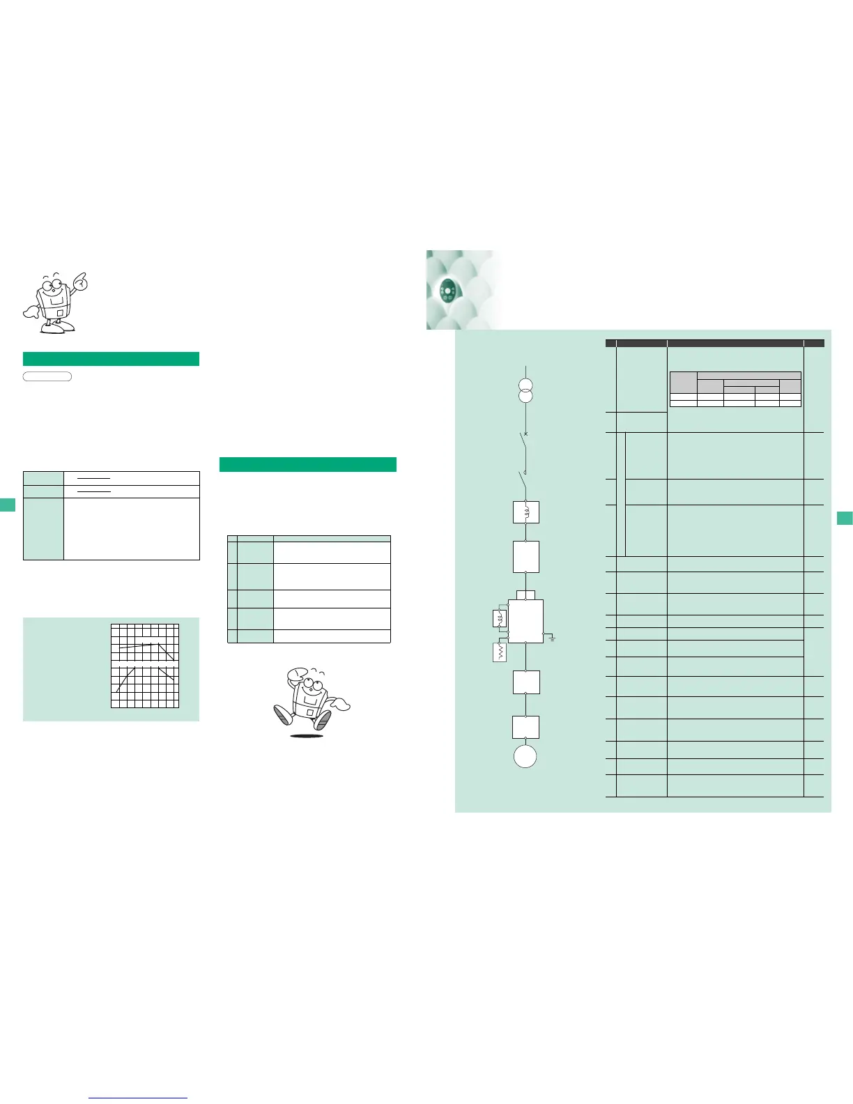
①
②
③
④
⑤
⑥
⑦
⑧
⑯
⑨
⑩
⑪
⑫
⑬
⑭
⑮
Input AC reactor (ACL)
DC reactor (DCL)
High-attenuation
radio noise filter
(NF type)
Braking resistor
Conduit pipe
attachment kit
Motor-end surge
voltage suppression filter
(for 500V class only)
Zero-phase reactor
ferrite core-type
EMC
noise filter
(Compliant with
European standards)
P.17
P.18
P.18
P. 9
P.20
P.20
P.19
-
-
P.18
P.19
-
P.19
P.19
P.20
Used to improve the input power factor, reduce the harmonics, and suppress
external surge on the inverter power source side. Install when the power
capacity is 200 kVA or more and 10 times or more than the inverter capacity
or when a distorted wave generation source such as a thyristor unit or a large-
capacity inverter is connected in the same distribution system.
Generally, a DC reactor improves the power factor more than a DC reactor.
When the inverter is used along with equipment for which a high degree of
reliability is required, an input AC reactor capable of suppressing external
surges should be used along with a DC reactor.
These types of filters are not necessary because all single-phase 240V or 3-
phase 500V models have a built-in EMI noise filter, conforming to Class A, as
standard. But install these filters if necessarily of noise reduction move and
more.
• Effective to prevent interference in audio equipment used near the inverter.
• Install on the input side of the inverter.
• Provided with wide-range attenuation characteristics from AM radio bands to
near 10MHz.
• Use when equipment readily affected by noise is installed in the peripheral
area.
• Effective to prevent interference in audio equipment used near the inverter.
• Effective in noise reduction on both input and output sides of the inverter.
• Provided with attenuation characteristics of several dB in frequencies from
AM radio bands to 10MHz.
• For noise countermeasures, insert on the secondary side of the inverter.
DIN rail kit
Parameter writer
Extension panel
RS232C
communication
conversion cable
Remote panel
A high-attenuation compact EMI noise filter that can be Foot-mounted and
Side-mounted. With this filter on, the inverter complies with the following
standards.
Three-phase 240V model:
EN55011: Class A, Group 1 (Motor connecting cable length: 5 m or less)
And EN55011: Class B, Group 1 (Motor connecting cable length: 1 m or less)
Single-phase 240V, three-phase 500V models:
EN55011: Class B, Group 1 (Motor connecting cable length: 20 m or less)
And EN55011: Class A, Group 1 (Motor connecting cable length: 50 m or less)
Use when rapid deceleration or stop is frequently required or when it is
desired to reduce the deceleration time with large load. This resistor consumes
regenerative energy during power generation braking.
• Braking resistor - With (resistor + protective thermal relay) built in.
Use this unit for batch read, batch copy, and batch writing of setting
parameters. (Model: PWU001Z)
Available for the 2.2kW (or 1.5kW) or less.
(Model: DIN003Z, DIN005Z)
Attachment kit used for conformance to NEMA TYPE1.
⑰
⑱
Communication
cable for totally
enclosed box type
This cable allows you to connect a personal computer for the totally enclosed
box type while retaining the protective construction of the IP54 (or IP55).
(Type: CAB 0031)
EMC plate
(attached as standard)
A steel plate used to connect shielded earth wires from inverter's power cables
or to connect earth wires from external devices.
Use an insulation-reinforced motor or install the surge voltage restraint filter to
prevent degrading motor insulation caused by surge voltage generation
depending on cable length and wiring method, or use of a 400V class motor
driven with an inverter.
Extended operation panel kit provided with LED indication section,
RUN/STOP key, UP/DOWN key, Monitor key, and Enter key.
(Model: RKP001Z)
Internal
communication
card
These boards allow you to connect a upper controller to multiple inverters for
data transfer. Removable terminal board is replaced by these boards. RS485,
DeviceNet and Lonworks are prepared.
(Models: RS4003Z, DEV001Z, LIU005Z)
This unit allows you to connect a personal computer to inverters for data
communications.
(Model: RS20035)
RS485
communication
conversion unit
USB
communication
conversion unit
This unit allows you to connect a personal computer to multiple inverters for
data transfer.
(Models: RS4001Z, RS4002Z)
This unit is connected to a PLC or a computer to enable data communications.
By connecting the connector cable, parameters can be easily adjusted, and
data easily saved and written.
(Type: USB 001Z)
This panel includes a frequency meter, a frequency regulator and RUN/STOP
(forward/reverse run)switches.
(Model: CBVR-7B1)
Radio noise reduction filter
① Input AC reactor
(ACL)
Molded-cace circuit
breaker (MCCB)
Power supply
Magnetic
contactor (MC)
③ High-attenuation
radio noise reduction
filter
④ Zero-phase reactor
ferrite core-type radio
noise reduction filter
⑨ DIN rail kit
⑥EMC plate
(attached as standard)
② DC reactor
(
DCL
)
N.F
N.F
VF-S11
④
Zero-phase reactor
ferrite core-type radio
noise reduction filter
IM
⑤ EMC
noise reduction
filter(Compliant
with European
standards)
⑦ Braking
resistor
⑧
Motor-end surge
voltage suppression filter
(for 500V class only)
Motor
No.
Device Function and purpose Refer to
○Large : Large effective. ○: effective.×: ineffective
Reactor type
Input AC reactor
DC reactor
○
○
○
○
Large
○
○
Large
○
×
Improvement of
power factor
Suppression of harmonic
Effect
Suppression
of external
surge
240V-4.0kW or less
Other model

 Loading...


