Possible to bring
into compliance with
IP55 specifications!
Totally enclosed box type
Totally enclosed box type
Totally enclosed box type
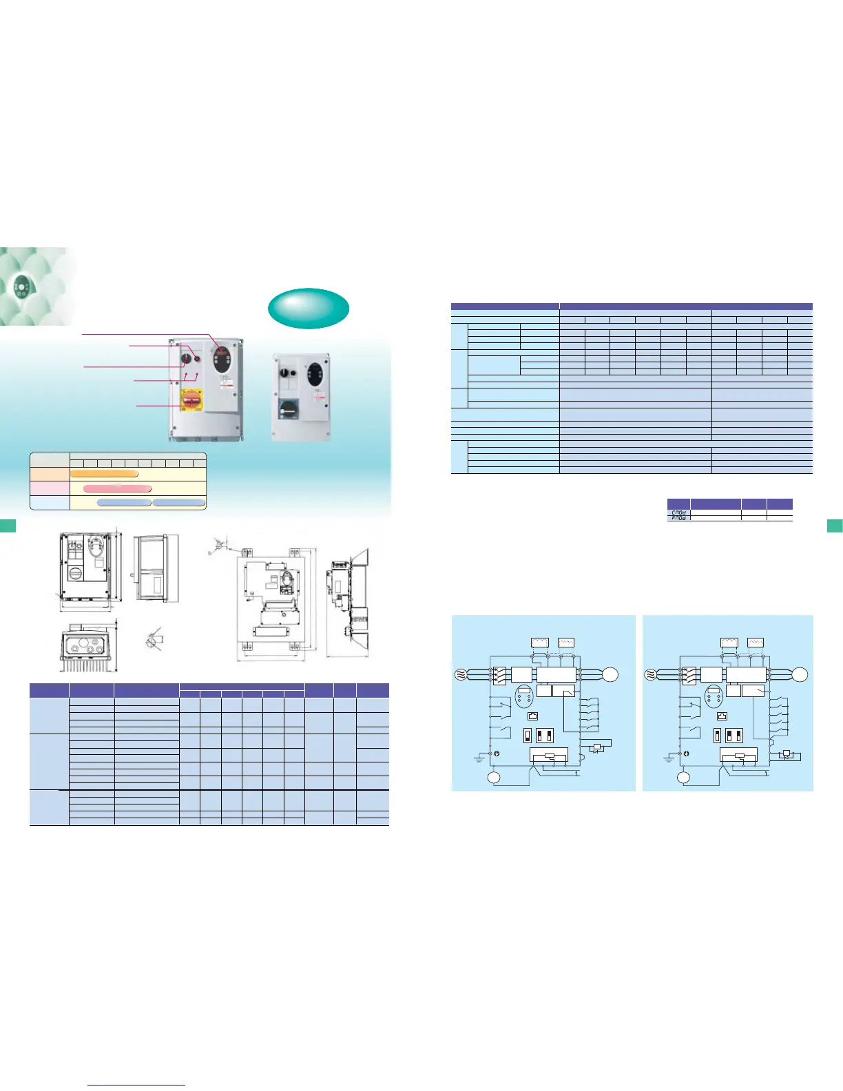
DC reactor (DCL)
❋
1 (option)
Braking resistor (option)
Sink (Negative) logic : Common = CC
❋1: The inverter comes with the PO and PA (positive) terminals short-circuited with a shorting bar. When connecting a DC reactor (DCL), detach the shorting bar.
❋2: When using the OUT output terminal in a sink logic configuration, do not short-circuit the NO and CC terminals.
❋3: When using the OUT output terminal in a sink logic configuration, do not short-circuit the P24 and OUT terminals.
Motor circuit breaker
R/L1
S/L2
T/L3
U/T1
V/T2
W/T3
Forward
Reverse
Reset
Preset-speed1
Preset-speed2
Preset-speed3
Common
Speed reach
signal output.
I M
FLC
FLB
FLA
RY
RC
PLC
Motor
F
R
RES
S1
S2
S3
CC
P24
OUT
NO
CC
FM
CC VIA VIB PP
+
+
−
−
P0
PA/+
PB PC/-
Meter
Voltage signal: 0-10V
(Current signal: 4-20mA)
Control
circuit
Operation switch
Fault detection relay
Ry
VF-S11
Frequency
meter
(ammeter)
Main circuit
Frequency setting potentiometer
Noise
filter
Low-speed
signal output
External 24Vdc
power input
Main circuit power supply
240V class:
1ph/3ph-200 to 240V
-50/60Hz
500V class:
3ph-380 to 500V
-50/60Hz
PLC
Connector for
common serial
communications
IISINK
SWI
SOURCE
FM
V
VIA
V
❋
2
DC reactor (DCL)
❋
1 (option)
Braking resistor (option)
Source (Positive) logic : Common = P24
Motor circuit breaker
R/L1
S/L2
T/L3
U/T1
V/T2
W/T3
Forward
Reverse
Reset
Preset-speed1
Preset-speed2
Preset-speed3
Common
Speed reach
signal output
I M
FLC
FLB
FLA
RY
RC
PLC
Motor
F
P24
OUT
NO
CC
R
RES
S1
S2
S3
FM
CC VIA VIB PP
+
+
−
−
P0
PA/+
PB PC/-
Meter
Voltage signal: 0-10V
(Current signal: 4-20mA)
Control
circuit
Operation switch
Fault detection relay
VF-S11
Frequency
meter
(ammeter)
Main circuit
Frequency setting potentiometer
Noise
filter
Low-speed
signal output
External 24Vdc
power input
Main circuit power supply
240V class:
1ph/3ph-200 to 240V
-50/60Hz
500V class:
3ph-380 to 500V
-50/60Hz
PLC
Connector for
common serial
communications
IISINK
SWI
SOURCE
FM
V
VIA
V
❋
3
Ry
■Standard connection diagram
Note 1: Capacity is calculated at 220V for the 240V class and at 440V for the 500V class.
Note 2: Indicates rated output current setting when the PWM carrier frequency (Parameter F300) is 4kHz or less. When exceeding 4kHz , the rated output current setting is indicated in the parenthesis.
Note 3: The maximum output voltage is equal to the input supply voltage.
Note 4: ±10% when the inverter is operated continuously (under a load of 100%).
Note 5: The factory default settings of the following parameters are different from those of the standard type.
The factory default settings of all other parameters are the same as those of the standard type.
For parameter settings, see the tables of parameters on page 10. periodically.
Note 6: Installation environment
・Install the inverter in a well-ventilated place and mount it on a flat metal plate in portrait orientation. Install the inverter so that it is not inclined more than ±10° from the vertical.
・Leave a space of 10 cm or more on the upper and lower sides of the inverter, and a space of 5 cm or more on each side.
・The inverter has a cooling fan to circulate air in it. The cooling fan has a useful life of approximately 30,000 hours (2 to 3 years when operated continuously), so it needs to be replaced
periodically.
●
Power switch for motor circuit breaker
●
Operation panel
●
Operation switch
●
Frequency setting potentiometer
●
Slots for additional switches (Two)
●
Totally enclosed structure compliant with IP54
●
Built-in noise filter
●
Equipped with all control devices as standard
(Control devices compliant with IP55
specifications / All-in-one)
●
Built-in motor circuit breaker
●
Minimum wiring
●
Cooling structure: Self-cooling type
22
21
Command mode selection
Frequency setting mode selection
1
0
Function
VF-S11
Standard type
0
2
VF-S11
otally enclosed type
Title
■External dimensions
Fig.F
3ph-240V
3ph-500V
1ph-240V
VFS11-2004PME
VFS11-2007PME
VFS11-2015PME
VFS11-2022PME
VFS11-2037PME
VFS11-4007PLE
VFS11-4015PLE
VFS11-4022PLE
VFS11-4037PLE
VFS11-4055PLU
VFS11-4075PLU
VFS11-4110PLU
VFS11-4150PLU
VFS11S-2002PLE
VFS11S-2004PLE
VFS11S-2007PLE
VFS11S-2015PLE
VFS11S-2022PLE
0.4
0.75
1.5
2.2
4.0
0.75
1.5
2.2
4.0
5.5
7.5
11
15
0.2
0.4
0.75
1.5
2.2
Input voltage
class
Aplicable motor
(kW)
Dimensions (mm)
W
Inverter type
Cabling hole
Drawing
Approx.weight
(kg)
210
215
230
215
230
400
450
210
215
230
H
240
297
340
297
340
600
700
240
297
340
D
163.3
192.3
208.3
192.3
208.3
243
267
163.3
192.3
208.3
192
197
212
197
212
310
340
192
197
212
218
277
320
277
320
570
670
218
277
320
13.7
13.7
13.7
13.7
13.7
-
-
13.7
13.7
13.7
3.9
5.9
7.6
F
F
F
G
G
F
F
6.1
17.0
4.0
8.0
11.8
6.0
7.6
W1
H1 D2
φ19x3
φ21x1
φ19x1
φ23x3
φ19x1
φ23x3
-
-
φ19x3
φ21x1
φ19x1
φ23x3
■Standard specifications
* Other specifications are the same as those of the standard type. See common specification on page 6.
Item
Input voltage class
Applicable motor (kW)
Protective method
Cooling method
Color
Built-in filter
Capacity(kVA)
Note 1)
Output voltage Note 3)
Overload current rating
Voltage-frequency
Allowable fluctuation
Service environments
Note 6)
Ambient temperature
Storage temperature
Relative humidity
Vibration
Input voltage class
1ph-240V class
3ph-240V class
3ph-500V class
Rated output current
(A)
Note 2)
Type
VFS11S-
VFS11-
VFS11-
1ph-240V class
3ph-240V class
3ph-500V class
ModelRating
Power
supply
Environments
Specification
1ph-240V input class / 3ph-240V input class / 3ph-500V input class
Form
3ph-500V input class
Form
Indoor, altitude 1000m or less. Place not exposed to direct sunlight and free from of corrosive and explosive gases.
240V class : 3ph-200V to 240V, 500V class : 3ph-380V to 500V
150% -60 seconds, 200% -0.5 second
240V class : 1ph/3ph-200V to 240V -50/60Hz,
500V class : 3ph-380V to 500V -50/60Hz
Voltage +10%, -15%
Note4), frequency ±5%
IP54 Totally enclosed type (JEM1030) /
Possible to bring into compliance with IP55
Self-cooling
Munsel 5Y-8/0.5
1ph and 500V class : High-attenuation EMI filter, 3ph-240V class : Basic filter
-10 to +40˚C
-25 to +70˚C
20 to 93%
5.9 m/s
2
or less (10 to 55Hz)
3ph -380V to 500V
150% -60 seconds, 200% -0.5 second
3ph-380V to 500V -50/60Hz
Voltage +10%, -15%
Note4)
, frequency ±5%
IP00 Open type (JEM1030) /
Cooling fin mountable out side
Forced air-cooling
Not painted
High-attenuation EMI filter
-10 to +40˚C
-25 to +70˚C
20 to 93%
5.9 m/s
2
or less (10 to 55Hz)
0.2
2002PLE
–
–
0.6
1.5 (1.5)
–
–
0.4
2004PLE
2004PME
–
1.3
3.3 (3.3)
3.3 (3.3)
–
0.75
2007PLE
2007PME
4007PLE
1.8
4.8 (4.4)
4.8 (4.4)
2.3 (2.1)
1.5
2015PLE
2015PLME
4015PLE
3.0/3.0/3.1
8.0 (7.9)
8.0 (7.9)
4.1 (3.7)
2.2
2022PLE
2022PME
4022PLE
4.2
11.0 (10.0)
11.0 (10.0)
5.5 (5.0)
4.0
–
2037PME
4037PLE
6.7/7.2
–
17.5 (16.4)
9.5 (8.6)
5.5
–
–
4055PLU
11
–
–
14.3 (13.0)
7.5
–
–
4075PLU
13
–
–
17.0 (17.0)
11
–
–
4110PLU
21
–
–
27.7 (25.0)
15
–
–
4150PLU
25
–
–
33 (30)
W1
(Mounting dimension)
W
9
H1 (
Mounting
dimension)
H
D
D2
10
R2.75
φ13
2-R2.75
■Compliance with IP55
IP54-compliant structures refer to structures that protect the contents from dust and harmful effects of water that drops from every direction. The inverter can be
brought into compliance with IP55 specifications by making the wiring port watertight. (IP55-compliant structures refer to structures that protect the contents from
dust and harmful effects of water that comes in a jet from every direction.)
Note) 500V class 5.5 to 15kW range are IP00 type.
D
W
15
R4
10
H
H1 (
Mounting
dimension)
W1
(Mounting dimension)
Fig.G
■Line-up
<ULcomplianttype>
Applicable motor (kW)
0.2 0.4 0.75 1.5 2.2 4.0 5.5 7.5 11 15
1-phase 240V
3-phase 240V
3-phase 500V
Input voltage
class
IP00IP54
IP54
IP54
■External dimensions

 Loading...


