- 10 - tousek / E_PULL-T5-T8-T10-T15_04 / 06. 08. 2019
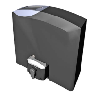
3.1 Terminal assignment Sliding gate operator PULL T5, -T8, -T10, -T15
Warning notes
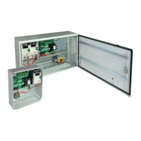
• Before taking o the control cover, the
mains switch must be turned o!
• If the control is power supplied, its inner part is under
tension.
• In order to avoid electrical strokes, the safety regula-
tions have to be kept.
• The device may only be connected by trained profes-
sionals.
• The product is not suitable for installation in explosion-
hazardous areas.
• An all-pole disconnecting mains switch with a contact
opening gap of min. 3 mm has to be foreseen. The
gate facility has to be secured according to the valid
safety regulations!
• IMPORTANT: The control lines (buttons, radio, pho-
tocells, etc.) have to be laid separately from the 230V
lines (supply line, motors, signal lamp).
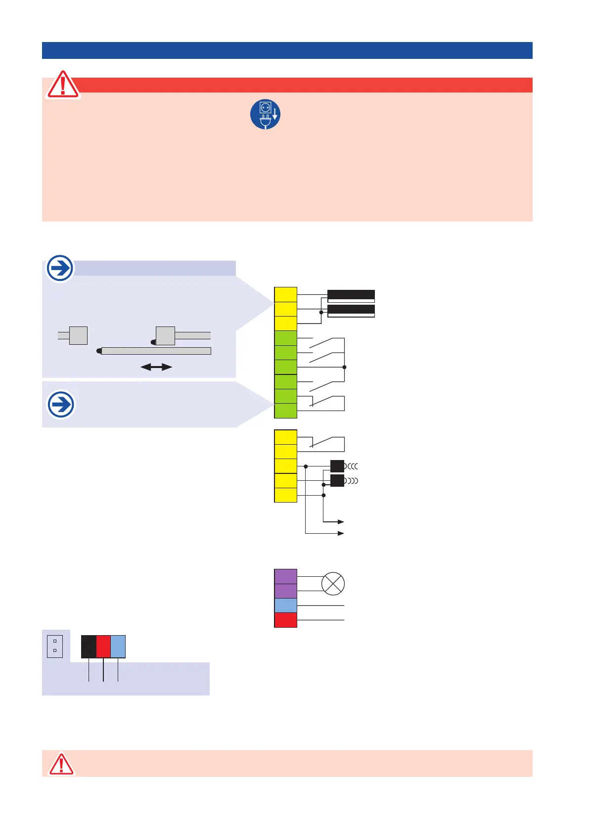
Signal lamp 230V, 100W
Power supply 230V a.c.
Contact for photocell
Common PHC-contact
Power supply photocell receiver
Power supply photocell transmitter
common photocell
Main safety sensing edge
Side safety sensing edge
common contact safety edge
Pedestrian-switch
CLOSE-switch
Common
Impulse-switch
STOP- contact
Power supply
max. 24Va.c., 5W
40
41
43
45
46
31
37
32
30
33
34
52
51
50
1
10
11
85
84
86
24V
~
L
N
8.k2
8.k2
L
N
black
motor connection
red
230Va.c.
blue
pre-wired
motor condenser
24V
~
N
The stop input has no emergency stop function! - In order to ensure the emergency stop function, provide
the supply line with an all-pole disconnecting emergency stop switch, that locks after actuation!
Safety sensing edges
Function main safety sensing edge (MCE):
Safety during closing
Function side safety sensing edges (SE):
Safety during opening
MCE
SE
CLOSE OPEN
If no stop switch is connected, termi-
nals 31/37 have to be wire-bridged.