tousek / E_PULL-T5-T8-T10-T15_04 / 06. 08. 2019 - 5 -
2
5a
11
3
1
4a
4
5
6
6a
6b
9
10
12
8
7
or
P
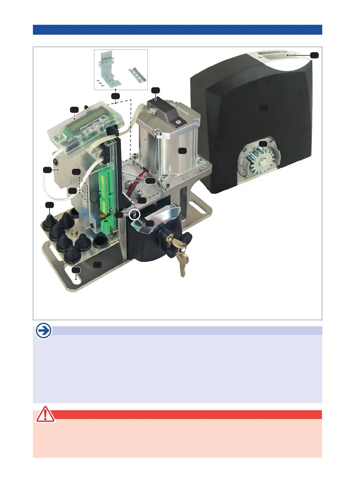
Technical layout PULL T5, -T8, -T10, -T15
2. Installation Sliding gate operator PULL T5, -T8, -T10, -T15
General installation notes
Before installing the Tousek PULL T5, -T8, -T10, -T15 sliding gate operator we recommend checking the following points:
• Checking the gate structure:
On a gate which travels on oor rails please check the bottom rollers and the upper guide rollers and make
sure that there is no undue friction or jamming.
On a cantilever gate please check if the gate can be moved out of its end-positions without undue eort.
• The gate must travel in a stable manner without lateral movements of the gate panel.
• Make sure that the gate travels in a regular way without undue friction or jamming along the whole travel length.
•
Make sure that there are stoppers at both ends of the track, preventing the gate from running over its travel limit.
(5) Control board
(Display and control buttons)
(5a) Removable display cover
(6) Control housing
(6a) Cover for optional, pluggable
radio module
(6b) Indication for opt. additional module
(7) Sensor
(8) Motor condenser
(9) Motor-/gear unit
(10) Threaded hole for attachment of
motor cover
(11) Motor cover
(12)
optional DIN rail or angle with DIN rail
can be bolted at position (P) 3x:
e.g. for two devices with 11 pole plug
socket
(1) Lockable emergency release (PHZ)
(2) Gear wheel
(3) Cable ttings
(4) Ground plate
(4a) Slotted holes (4x) for mounting on
the foundation/ground
ATTENTION !
• ATTENTION: Mechanical limits are necessary!
• ATTENTION: the sliding gate operator PULL T5, -T8, -T10, -T15 has been developed and designed for the au-
tomation of horizontally travelling sliding gates. Gates on sloping tracks (i.e. gates which follow an inclined,
non-horizontal, travel path) must not be automated without additional safety devices (which make sure that
the gate cannot start moving on its own from any gate position).