24
Adjustment of respective parts
3.Adjustment of respective parts
1.Needle bar position
Needle bar height
[Condition]
Needle: # 14
[Diagnosis]
1. Remove the extension table, and open the
shuttle cover.
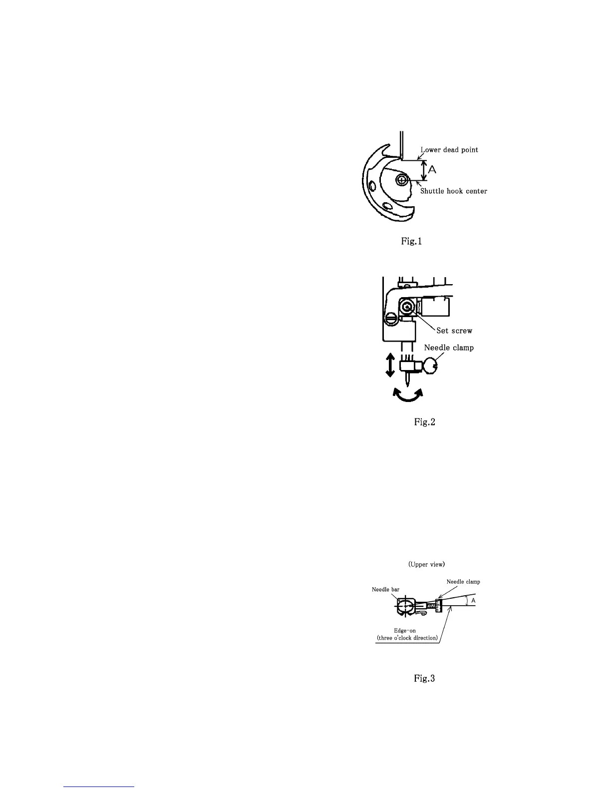
2. When the needle bar is brought to the lower
dead point by rotating the handweel, mea-
sure the clearance (A) between the needle
point and the shuttle hook center.(Fig. 1)
[Standard]
A = 11.2 ± 0.2 mm (Fig.1)
* Make adjustment if the diagnosis result fails to
meet the standard.
[Adjustment]
1. Turn the handweel, bring the needle bar to
the lower dead point.
2. Loosen the set screw, adjust the height and
direction of needle bar.(Fig. 2)
3. Tighten the set screw.(Fig. 2)
[Note]
After adjusting the height, confirm the orienta-
tion of needle bar as described in the next
step.
When the needle threader is equipped, con-
firm that the thread passes through properly.
(See:page.23)
* Repeat the adjustment till the standard is met.
Needle bar direction
[Diagnosis]
1. Remove the face cover.(See:page.45)
2. Check the needle clamp position.(Fig. 3)
3. When seeing from the top, measure the angle
(A) in the figure.(Fig. 3)
[Standard]
Needle clamp position:
Just beside when seeing from the top (Fig. 3)
(Right side seeing from the front)
A = 0° to 1.5° (Fig.3)
* Make adjustment if the diagnosis result fails to
meet the standard.