Do you have a question about the Toyota 2VZ-FE and is the answer not in the manual?
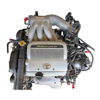
| Engine Type | V6 |
|---|---|
| Compression Ratio | 9.0:1 |
| Fuel System | Multi-Point Fuel Injection |
| Fuel Type | Gasoline |
| Valvetrain | DOHC, 4 valves per cylinder |
| Block Material | Cast Iron |
| Head Material | Aluminum |
| Displacement | 2.5 L |
| Bore x Stroke | 87.5 mm x 69.2 mm (3.44 in x 2.72 in) |
Preparation steps and special service tools for engine mechanical tasks.
Lists special service tools required for engine mechanical procedures.
Covers inspections and adjustments related to engine tune-up procedures.
Details the process for inspecting and adjusting engine valve clearance.
Provides charts for selecting appropriate shims for valve clearance adjustment.
Specific information related to intake system adjustments and specifications.
Procedure for inspecting and adjusting the engine's ignition timing.
Guidance for diagnosing and resolving engine mechanical problems.
Procedure for checking the compression pressure of engine cylinders.
Overview of components related to the engine's timing belt system.
Step-by-step instructions for removing the engine timing belt.
Details on inspecting various components of the timing belt system.
Procedure for installing the engine timing belt and related components.
Diagram and list of components related to the engine cylinder heads.
Instructions for the removal of the engine cylinder heads.
Steps for disassembling the engine cylinder heads.
Procedures for inspecting, cleaning, and repairing cylinder head parts.
Guide for inspecting camshafts and their associated bearings.
Instructions for the reassembly of engine cylinder heads.
Procedure for installing the engine cylinder heads.
Steps for removing the engine assembly from the cylinder block.
Diagram and list of components related to the cylinder block.
Preparation steps before disassembling the cylinder block.
Detailed instructions for disassembling the cylinder block.
Procedures for inspecting and repairing the engine crankshaft.
Steps for assembling the piston and connecting rod assemblies.
Instructions for the reassembly of the cylinder block.
Procedure for installing the engine assembly into the vehicle.
Compilation of technical specifications and values for service.
General description of the Electronic Fuel Injection system.
Lists special service tools and recommended equipment for EFI system.
Diagram illustrating the EFI system's electrical circuit operation.
Description of the EFI system's fuel supply operation.
Explanation of the EFI system's air intake and control.
Overview of the EFI system's electronic control unit and sensors.
Important precautions for EFI system inspection and maintenance.
Detailed information and procedures for the EFI fuel system.
Description and inspection of the EFI system's fuel pump.
Steps for removing the EFI system's fuel pump.
Information on the EFI system's cold start injector.
Details on the EFI system's fuel pressure regulator.
Information regarding EFI system injectors, including inspection.
Procedure for removing the EFI system injectors.
Steps for inspecting the EFI system injectors.
Procedure for installing the EFI system injectors.
Diagram and list of components for the EFI fuel tank and lines.
Details on the EFI system's air flow meter.
Information and inspection of the EFI system's throttle body.
Inspection and service procedures for the EFI system's ISC valve.
Layout and terminal identification for the EFI system's ECU.
Procedures for inspecting the EFI system's Electronic Control Unit.
Inspection procedure for the EFI system's fuel cut RPM.
Diagram and list of components for exhaust pipes and heat insulators.
Overview of emission control systems and their purposes.
Layout and schematic diagrams of emission control systems.
Details on the PCV system for emission control.
Procedure for inspecting the PCV valve.
Explanation of the EVAP system for fuel emissions control.
Procedure for inspecting the charcoal canister in the EVAP system.
Details on the EGR system for emission control.
Procedures for inspecting the EGR system components.
Information on the three-way catalyst system for emission control.
General description of the engine cooling system.
Explanation of how the engine cooling system operates.
Recommended tools for cooling system preparation.
Procedure for checking and replacing engine coolant.
Diagram and list of components for the water pump.
Step-by-step instructions for removing the water pump.
Procedure for inspecting the water pump.
Procedure for removing the engine thermostat.
Instructions for cleaning the engine radiator.
Procedure for inspecting the radiator and its components.
Steps for removing the engine radiator.
Procedure for installing the engine radiator.
Diagram of the electric cooling fan system circuit.
Location of electric cooling fan system components.
On-vehicle inspection procedures for electric cooling fans.
Inspection steps for cooling fans at low temperatures.
Inspection of individual electric cooling fan components.
General description of the engine lubrication system.
Explanation of how the engine lubrication system operates.
Description and operation of the engine oil pump.
Special service tools and equipment for lubrication system prep.
Procedure for checking engine oil pressure.
Steps for replacing engine oil and the oil filter.
Instructions for removing the engine oil pump.
Steps for disassembling the engine oil pump.
Procedures for inspecting the engine oil pump.
Instructions for assembling the engine oil pump.
Procedure for installing the engine oil pump.
General precautions for the ignition system.
Overview of the ignition system's components and function.
Special service tools for ignition system preparation.
Procedure for performing a spark test on the ignition system.
Inspection procedures for high-tension ignition cords.
Inspection procedures for the ignition coil.
Inspection procedures for the ignition system distributor.
Diagram and list of distributor components.
Steps for removing the ignition system distributor.
Procedure for installing the ignition system distributor.
Procedure for adjusting the engine's ignition timing.
General guidelines on how to approach engine troubleshooting.
Using diagnostic tools for troubleshooting engine control system issues.
Customer problem analysis form for engine control system issues.
Explanation of the engine's diagnostic system.
Procedure for checking the 'CHECK' engine warning light.
List and explanation of diagnostic trouble codes for the engine.
Methods for simulating symptoms to diagnose intermittent problems.
Identification of ECU connector terminals for troubleshooting.
Chart correlating diagnostic codes with inspection circuits.
Fundamental checks to perform before detailed troubleshooting.
Chart correlating problem symptoms with relevant systems.
Detailed circuit inspection procedures for diagnosing faults.
Troubleshooting steps for diagnostic code 12 (RPM Signal).
Circuit description for diagnostic code 16 (ECT Control Signal).
Step-by-step inspection procedures for troubleshooting.
Circuit description for diagnostic code 22 (Water Temp. Sensor).
Inspection steps for diagnosing water temperature sensor issues.
Circuit description for diagnostic code 24 (Intake Air Temp. Sensor).
Inspection steps for diagnosing intake air temp. sensor issues.
Circuit description for air-fuel ratio lean/rich malfunctions.
Diagnostic chart for air-fuel ratio lean/rich malfunctions.
Inspection steps for air-fuel ratio related faults.
Circuit description for diagnostic code 27 (Sub-Oxygen Sensor).
Diagnostic chart for sub-oxygen sensor faults.
Inspection steps for diagnosing sub-oxygen sensor issues.
Circuit description for diagnostic codes 31/32 (Air Flow Meter).
Inspection steps for diagnosing air flow meter issues.
Circuit description for diagnostic code 41 (Throttle Position Sensor).
Inspection steps for diagnosing throttle position sensor issues.
Circuit description for diagnostic code 42 (Vehicle Speed Sensor).
Inspection steps for diagnosing vehicle speed sensor issues.
Circuit description for diagnostic code 43 (Starter Signal).
Inspection steps for diagnosing starter signal issues.
Circuit description for diagnostic code 52 (Knock Sensor).
Driving pattern for detecting knock sensor malfunctions.
Diagnostic chart for knock sensor issues.
Inspection steps for diagnosing knock sensor issues.
Circuit description for diagnostic code 53 (Knock Control).
Diagnostic chart for knock control system issues.
Circuit description for diagnostic code 71 (EGR System).
Driving pattern for detecting EGR system malfunctions.
Diagnostic chart for EGR system malfunctions.
Inspection steps for diagnosing EGR system issues.
Circuit description for diagnostic code 51 (Switch Condition).
Diagnostic chart for switch condition signals.
Inspection steps for diagnosing switch condition signals.
Inspection steps for diagnosing throttle position sensor signals.
Diagram and list of components for exhaust pipes and heat insulators.
Overview of emission control systems and their purposes.
Layout and schematic diagrams of emission control systems.
Details on the PCV system for emission control.
Procedure for inspecting the PCV valve.
Explanation of the EVAP system for fuel emissions control.
Procedure for inspecting the charcoal canister in the EVAP system.
Details on the EGR system for emission control.
Procedures for inspecting the EGR system components.
Information on the three-way catalyst system for emission control.
General description of the engine cooling system.
Explanation of how the engine cooling system operates.
Recommended tools for cooling system preparation.
Procedure for checking and replacing engine coolant.
Diagram and list of components for the water pump.
Step-by-step instructions for removing the water pump.
Procedure for inspecting the water pump.
Procedure for removing the engine thermostat.
Instructions for cleaning the engine radiator.
Procedure for inspecting the radiator and its components.
Steps for removing the engine radiator.
Procedure for installing the engine radiator.
Diagram of the electric cooling fan system circuit.
Location of electric cooling fan system components.
On-vehicle inspection procedures for electric cooling fans.
Inspection steps for cooling fans at low temperatures.
Inspection of individual electric cooling fan components.
General description of the engine lubrication system.
Explanation of how the engine lubrication system operates.
Description and operation of the engine oil pump.
Special service tools and equipment for lubrication system prep.
Procedure for checking engine oil pressure.
Steps for replacing engine oil and the oil filter.
Instructions for removing the engine oil pump.
Steps for disassembling the engine oil pump.
Procedures for inspecting the engine oil pump.
Instructions for assembling the engine oil pump.
Procedure for installing the engine oil pump.
General precautions for the ignition system.
Overview of the ignition system's components and function.
Special service tools for ignition system preparation.
Procedure for performing a spark test on the ignition system.
Inspection procedures for high-tension ignition cords.
Inspection procedures for the ignition coil.
Inspection procedures for the ignition system distributor.
Diagram and list of distributor components.
Steps for removing the ignition system distributor.
Procedure for installing the ignition system distributor.
Procedure for adjusting the engine's ignition timing.
General guidelines on how to approach engine troubleshooting.
Using diagnostic tools for troubleshooting engine control system issues.
Customer problem analysis form for engine control system issues.
Explanation of the engine's diagnostic system.
Procedure for checking the 'CHECK' engine warning light.
List and explanation of diagnostic trouble codes for the engine.
Methods for simulating symptoms to diagnose intermittent problems.
Troubleshooting technique using vibration to trigger faults.
Identification of ECU connector terminals for troubleshooting.
Chart correlating diagnostic codes with inspection circuits.
Fundamental checks to perform before detailed troubleshooting.
Chart correlating problem symptoms with relevant systems.
Detailed circuit inspection procedures for diagnosing faults.
Troubleshooting steps for diagnostic code 12 (RPM Signal).
Circuit description for diagnostic code 16 (ECT Control Signal).
Step-by-step inspection procedures for troubleshooting.
Circuit description for diagnostic code 22 (Water Temp. Sensor).
Inspection steps for diagnosing water temperature sensor issues.
Circuit description for diagnostic code 24 (Intake Air Temp. Sensor).
Inspection steps for diagnosing intake air temp. sensor issues.
Circuit description for air-fuel ratio lean/rich malfunctions.
Diagnostic chart for air-fuel ratio lean/rich malfunctions.
Inspection steps for air-fuel ratio related faults.
Circuit description for diagnostic code 27 (Sub-Oxygen Sensor).
Diagnostic chart for sub-oxygen sensor faults.
Inspection steps for diagnosing sub-oxygen sensor issues.
Circuit description for diagnostic codes 31/32 (Air Flow Meter).
Inspection steps for diagnosing air flow meter issues.
Circuit description for diagnostic code 41 (Throttle Position Sensor).
Inspection steps for diagnosing throttle position sensor issues.
Circuit description for diagnostic code 42 (Vehicle Speed Sensor).
Inspection steps for diagnosing vehicle speed sensor issues.
Circuit description for diagnostic code 43 (Starter Signal).
Inspection steps for diagnosing starter signal issues.
Circuit description for diagnostic code 52 (Knock Sensor).
Driving pattern for detecting knock sensor malfunctions.
Diagnostic chart for knock sensor issues.
Inspection steps for diagnosing knock sensor issues.
Circuit description for diagnostic code 53 (Knock Control).
Diagnostic chart for knock control system issues.
Circuit description for diagnostic code 71 (EGR System).
Driving pattern for detecting EGR system malfunctions.
Diagnostic chart for EGR system malfunctions.
Inspection steps for diagnosing EGR system issues.
Circuit description for diagnostic code 51 (Switch Condition).
Diagnostic chart for switch condition signals.
Inspection steps for diagnosing switch condition signals.
Inspection steps for diagnosing throttle position sensor signals.