DIAGNOSIS
- "CHECK
ENGINE" Lamp and VF or VF1 Terminal Output
2
. VF OR VF1 TERMINAL OUTPU
T
OUTPUT OF AIR-FUEL RATIO FEEDBACK
CORRECTION (T, TE1 or TE2 terminal off
)
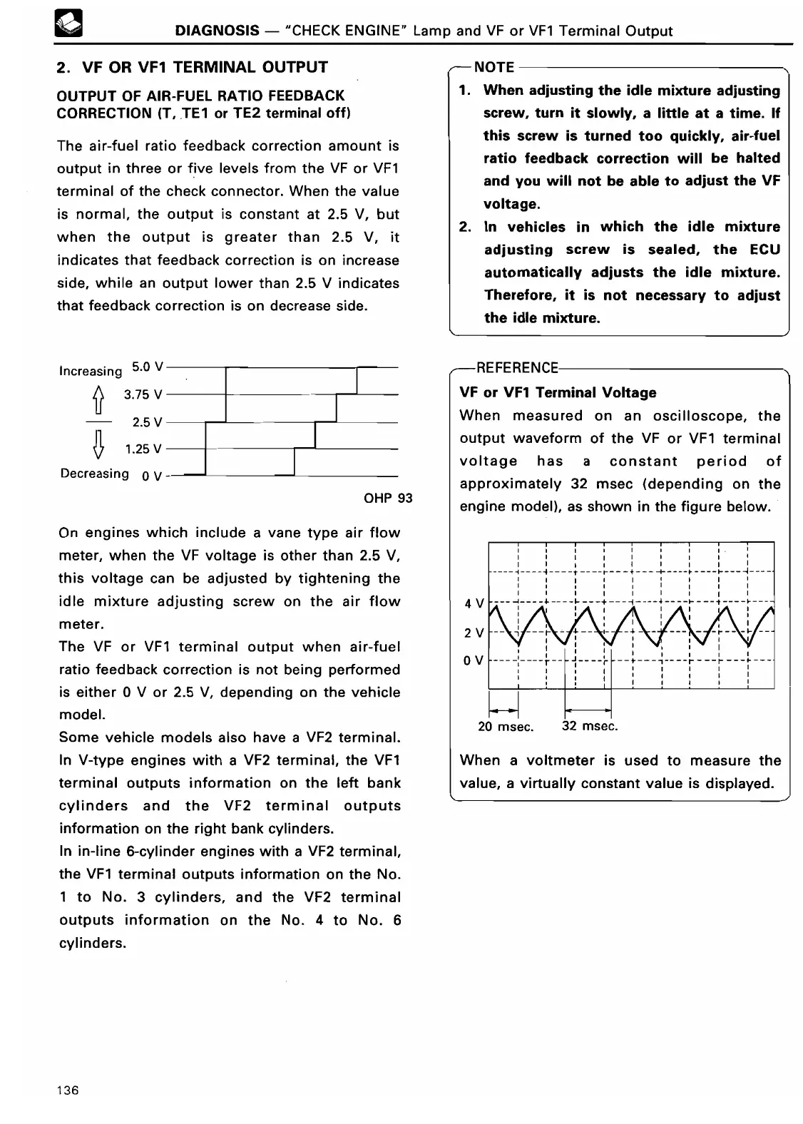
The air-fuel ratio feedback correction amount is
output in three or five levels from the VF or VF1
terminal of the check connector
. When the value
is normal, the output is constant at 2
.5 V, but
when the output is greater than 2
.5 V, it
indicates that feedback correction is on increase
side, while an output lower than 2
.5 V indicates
that feedback correction is on decrease side
.
Increasing 5
.0 V
3
.75
V
2
.5 V
1
.25
V
Decreasing
0V
OHP 9
3
On engines which include a vane type air flow
meter, when the VF voltage is other than 2
.5 V,
this voltage can be adjusted by tightening the
idle mixture adjusting screw on the air flow
m ete r
.
The VF or VF1 terminal output when air-fuel
ratio feedback correction is not being performed
is either 0 V or 2
.5 V, depending on the vehicle
model
.
Some vehicle models also have a VF2 terminal
.
In V-type engines with a VF2 terminal, the VF1
terminal outputs information on the left bank
cylinders and the VF2 terminal outputs
information on the right bank cylinders
.
In in-line 6-cylinder engines with a VF2 terminal,
the VF1 terminal outputs information on the No
.
1 to No
. 3 cylinders, and the VF2 terminal
outputs information on the No
. 4 to No
. 6
cylinders
.
T
E
1
. When adjusting the idle mixture adjusting
screw, turn it slowly, a little at a time
. If
this screw is turned too quickly, air-fuel
ratio feedback correction will be halted
and you will not be able to adjust the VF
voltage
.
2
. In vehicles in which the idle mixture
adjusting screw is sealed, the ECU
automatically adjusts the idle mixture
.
Therefore, it is not necessary to adjust
the idle mixture
.
-REFERENCE
VF or VF1 Terminal Voltag
e
When measured on an oscilloscope, the
output waveform of the VF or VF1 terminal
voltage has
a constant
period of
approximately 32 msec (depending on the
engine model), as shown in the figure below
.
4
V
2
V
0V
20 msec
.
I I I
__
1
+---
i
32 msec
.
When a voltmeter is used to measure the
value, a virtually constant value is displayed
.
136