DIAGNOSIS
- "CHECK
ENGINE" Lamp and VF or VF1 Terminal Output
OXYGEN SENSOR SIGNAL OUTPUT IT or TE1
terminal on, TE2 terminal off, idle contact off
)
To read the output of the oxygen sensor,
connect terminal T or TE1 with terminal
El, with
the idle contact off
. Then measure the voltage at
the VF or VF1 terminal
. (The output from this
terminal is not the actual signal that is output by
the oxygen sensor, but a signal that has been
digitalized by the ECU for easier reading
.
)
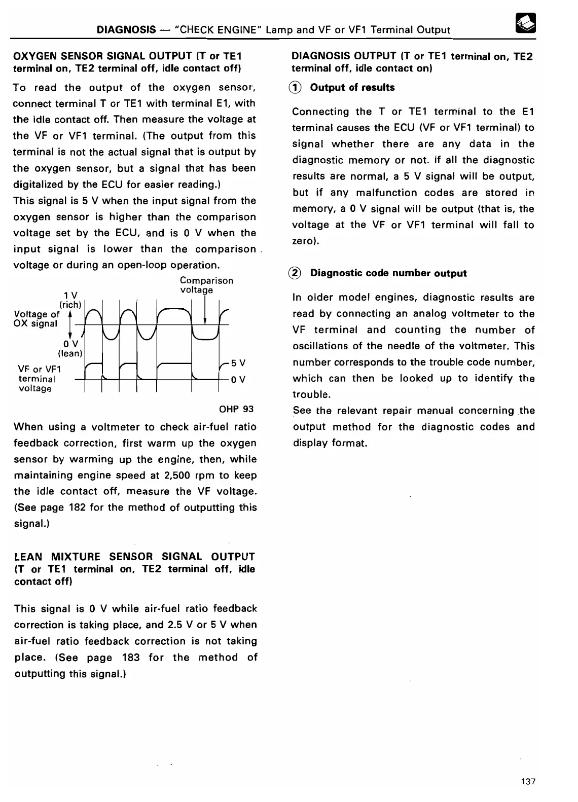
This signal is 5 V when the input signal from the
oxygen sensor is higher than the comparison
voltage set by the ECU, and is 0 V when the
input signal is lower than the comparison
voltage or during an open-loop operation
.
Comparison
voltag
e
0V
(lean
)
VF or VF1
terminal
voltage
OHP 93
When using a voltmeter to check air-fuel ratio
feedback correction, first warm up the oxygen
sensor by warming up
the engine,
then, while
maintaining engine speed
at 2,500 rpm to keep
the idle contact off, measure the VF voltage
.
(See page 182
for the method of outputting this
signal
.
)
LEAN MIXTURE
SENSOR
SIGNAL OUTPUT
(T or TE1 terminal
on, TE2 terminal off, idle
contact off
)
This signal is 0 V while air-fuel ratio feedback
correction is taking place, and 2
.5 V or 5 V when
air-fuel ratio feedback correction is not taking
place
. (See page 183 for the method of
outputting this signal
.)
DIAGNOSIS OUTPUT (T or TE1 terminal on, TE2
terminal off, idle contact on
)
J Output of
result
s
Connecting the T or TE1 terminal to the
El
terminal causes the ECU (VF or VF1 terminal) to
signal whether there are any data in the
diagnostic memory or not
. If all the diagnostic
results are normal, a 5 V signal will be output,
but if any malfunction codes are stored in
memory, a 0 V signal will be output (that is, the
voltage at the VF or VF1 terminal will fall to
zero)
.
~2 Diagnostic
code number outpu
t
In older model engines, diagnostic results are
read by connecting an analog voltmeter to the
VF terminal and counting the number of
oscillations of the needle of the voltmeter
. This
number corresponds to the trouble code number,
which can then be looked up to identify the
trouble
.
See the relevant repair manual concerning the
output method for the diagnostic codes and
display format
.
137