W
INSPECTION AND ADJUSTMENT
- Throttle Position Sensor and Throttle Bod
y
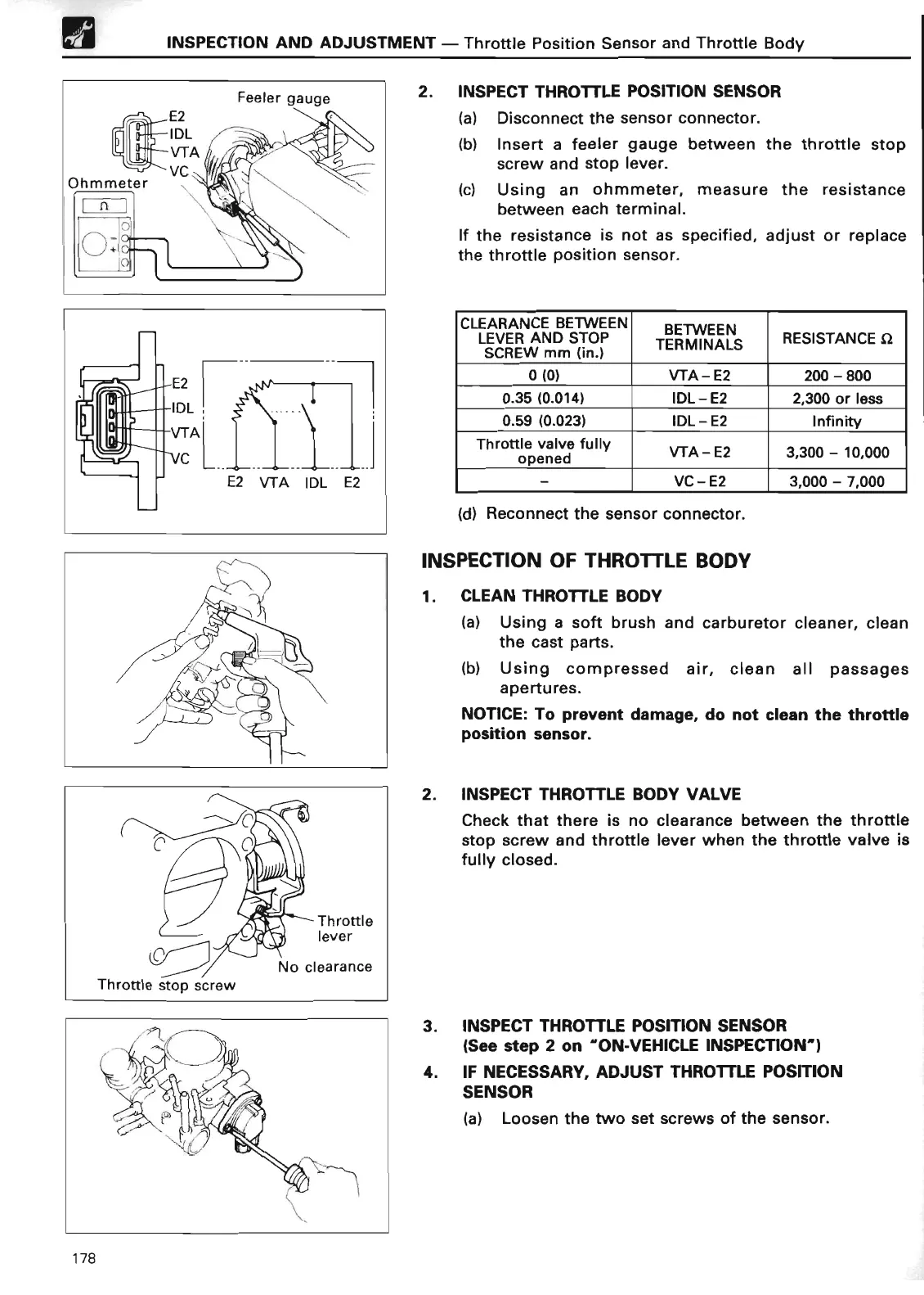
E2
IDL
VTA
E2 VTA IDL E2
2
. INSPECT THROTTLE
POSITION SENSOR
(a) Disconnect the sensor connector
.
(b) Insert a feeler gauge between the throttle stop
screw and stop lever
.
(c) Using an ohmmeter, measure the resistance
between each terminal
.
If the resistance is not as specified, adjust or replace
the throttle position sensor
.
CLEARANCE
BETWEEN
BETWEE
N
LEVER AND STOP
TERMINALS
RESISTANCE S
2
SCREW mm (in
.
)
0(0)
VTA - E2
200 - 80
0
0.35 (0
.014) IDL
-
E2
2,300 or les
s
0
.59 (0
.023)
IDL - E2
Infinit
y
Thro
tt
le valve full
y
opened
y fA-E2
3,300
-
10,00
0
-
VC-E2
3,000 - 7,00
0
(d) Reconnect the sensor connector
.
INSPECTION OF THROTTLE BOD
Y
1
. CLEAN
THROTTLE BOD
Y
(a) Using a soft brush and carburetor cleaner, clean
the cast parts
.
(b) Using compressed air, clean all passages
apertures
.
NOTICE
: To
prevent damage, do not clean the throttle
position sensor
.
2
. INSPECT THROTTLE BODY VALV
E
Check that there is no clearance between the throttle
stop screw and throttle lever when the throttle valve is
fully closed
.
3
. INSPECT THROTTLE
POSITION SENSOR
(
See step 2 on "ON-VEHICLE INSPECTION"
)
4
. IF NECESSARY,
ADJUST THROTTLE POSITION
SENSO
R
(a) Loosen the two set screws of the sensor
.
178