INSPECTION AND ADJUSTMENT
- Throttle Position Sensor and Throttle Body
W
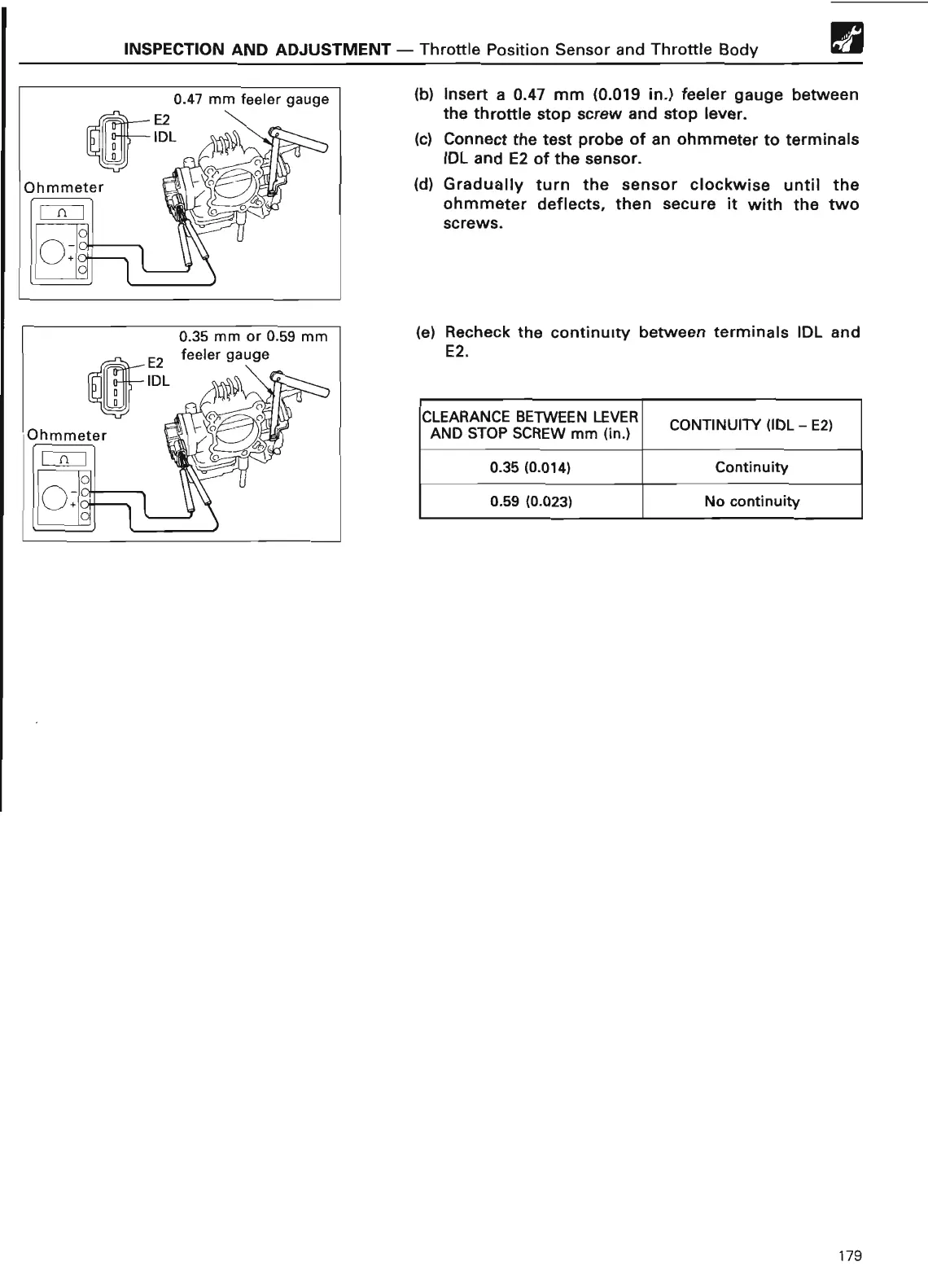
(b) Insert a 0
.47 mm (0
.019 in
.) feeler gauge between
the throttle stop screw and stop lever
.
(c) Connect the test probe of an ohmmeter to terminals
IDL and E2 of the sensor
.
(d) Gradually turn the sensor clockwise until the
ohmmeter deflects, then secure it with the two
screws
.
(e) Recheck the continuity between terminals IDL and
E2
.
CLEARANCE BETWEEN LEVER
CONTINUITY (IDL - E2
)
AND STOP SCREW mm (in
.
)
0.35 (0
.014)
Continuit
y
0
.59 (0
.023)
No continuity
179