ELECTRONIC CONTROL SYSTEM
- G and NE Signal Generator
s
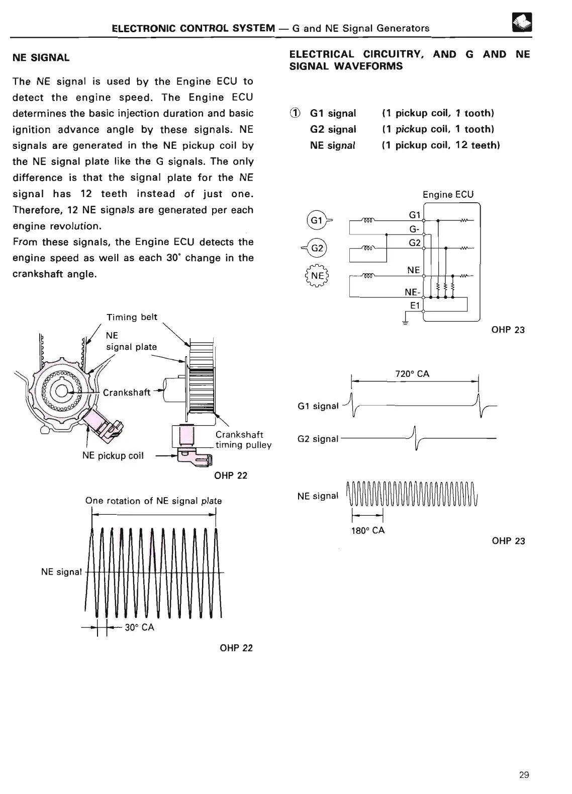
NE SIGNAL
F*
1
ELECTRICAL CIRCUITRY, AND G AND NE
SIGNAL WAVEFORM
S
The NE signal is used by the Engine ECU to
detect the engine speed
. The Engine EC
U
determines the basic injection duration and basic G1
signal
(1 pickup coil, 1 tooth)
ignition advance angle by these signals
. NE G2 signal (1 pickup coil, 1 tooth)
signals are
generated in the NE pickup coil by
NE signal
(
1 pickup coil,
12 teeth
)
the NE signal plate like the G signals
. The only
difference is that the signal plate for the NE
signal has 12 teeth instead of just one
.
Therefore, 12 NE signals are generated per each
engine revolution
.
From these signals, the Engine ECU detects the
engine speed as well as each 30° change in the
crankshaft angle
.
Engine ECU
OHP 23
NE pickup coil
rfimmimlii~
OHP 2
2
One rotation of NE
signal plat
e
NE signal
h
I
1
~r~rrur~
r
i ~
►
- 30° CA
irr
OHP 22
F
G1 signa
l
G2 signa
l
NE signal
1800
CA
7200
CA
J
OHP 23
29