❑
ELECTRONIC CONTROL SYSTEM
- G and NE Signal Generator
s
©
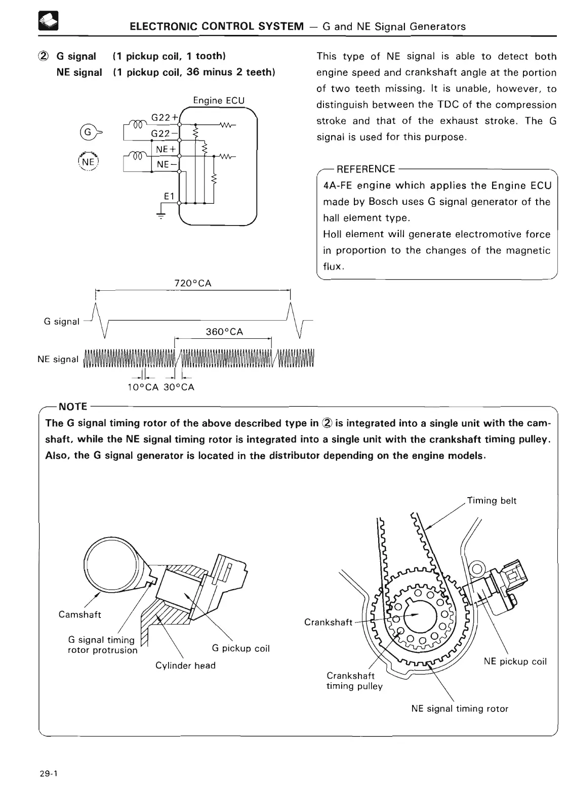
G signal
(1 pickup coil, 1 tooth
)
NE signal
(1 pickup coil, 36 minus 2 teeth
)
Engine EC
U
e~N
(NE
This type of NE signal is able to detect both
engine speed and crankshaft angle at the portion
of two teeth missing
. It is unable, however, to
distinguish between the TDC of the compression
stroke and that of the exhaust stroke
. The G
signal is used for this purpose
.
,,--
REFERENC
E
4A-FE engine which applies the Engine ECU
made by Bosch uses G signal generator of the
hall element type
.
Holl element will generate electromotive force
in proportion to the changes of the magnetic
flux
.
I
G signa
l
NE signal
YYVV
W
Y
720°C
A
360°C
A
V
_I
L
--
I
L
10°CA 30°CA
7
VVVYYVYYVVYVVY YtlYYVVVYYVYYYVVVYVYYYVYVYVYtlYYYY YVVVVYtlVVYVVY
/
NOTE
The G signal timing rotor of the above described type in Z) is integrated into a single unit with the cam-
shaft, while the NE signal timing rotor is integrated into a single unit with the crankshaft timing pulley
.
Also, the G signal generator is located in the distributor depending on the engine models
.
Camshaft
A~B
R
A A ~ a 0 ~
I
G pickup coi
l
Cylinder head
NE signal timing rotor