EFI - Functions
of Engine EC
U
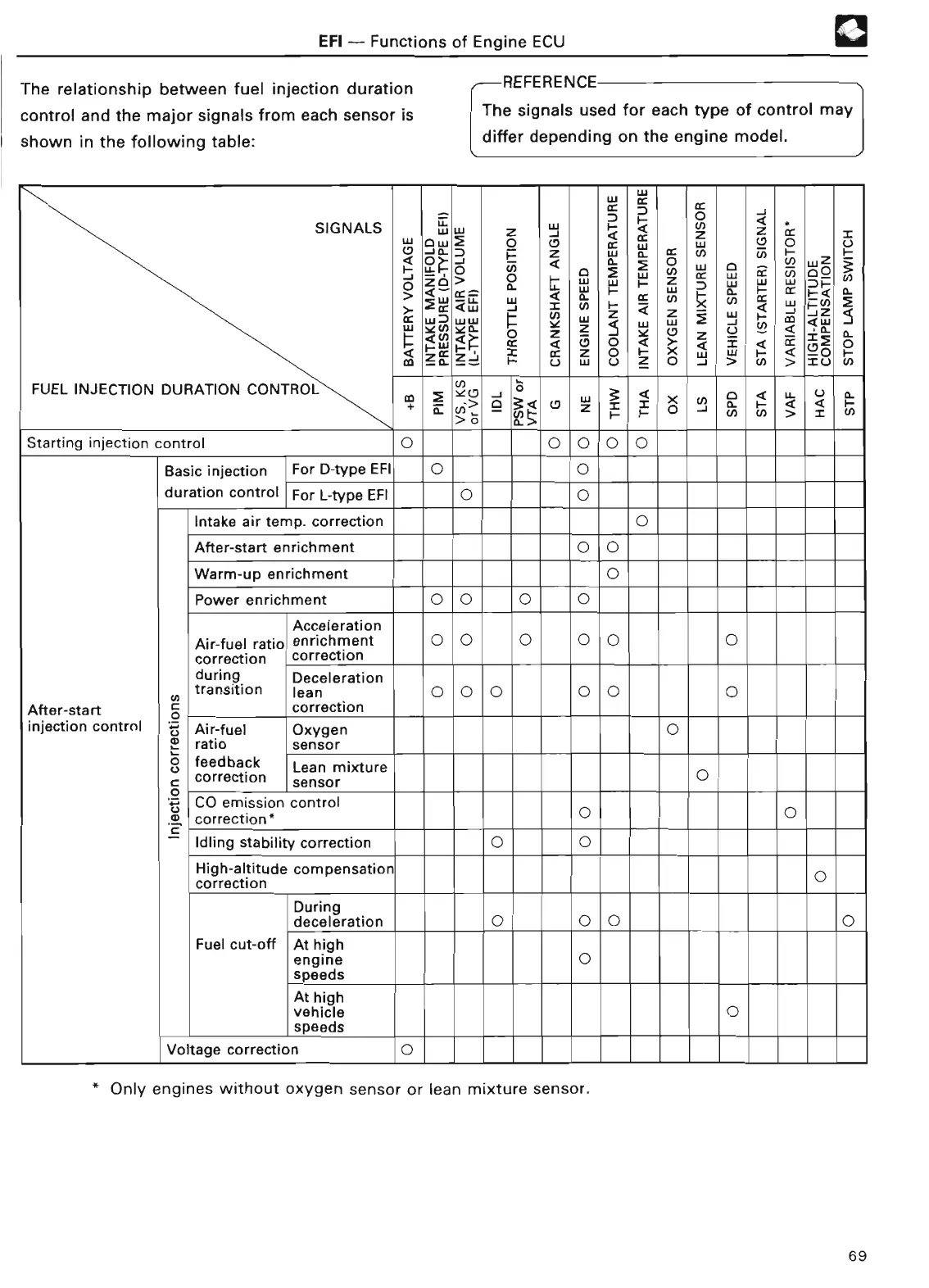
The relationship between fuel injection duration
control and the major signals from each sensor is
shown in the following table
:
®
REFERENCE
The signals used for each type of control may
differ depending on the engine model
.
N
SIGNALS
w w
0
_J a
.
P
:
z
W
a-
CC
U)
7
h
H
L
L
U
_J
(
L
M
V)
x
v)
cc
~
w
D
xN
w
w
xa
d
=
¢~
H
C7
p
za
?d
xu
FUEL INJECTION DURATION CONTROL
m
Neu
0
0
U_
(
L
;
o
Z
0
w
M
N
j
=
N
a
s
Starting injection
control
0
0
0 0 0
Basic injection
For D-type EFI
0 0
duration control
For L-type EFI
0
11
0
Intake air temp
. correction
0
After-sta
rt
enrichment
0 0
Warm-up enrichment
0
Power
enrichment
0
0 0
0
Acceleratio
n
Air-fuel ratio
enrichment
0 0 0
0 0 0
correction
correctio
n
during
Deceleratio
n
transition
lean
0 0 0 0 0 0
After-sta
rt
correctio
n
injection control
Air-fuel
Oxygen
0
42
ratio
senso
r
feedback
Lean mixture
0
correction
senso
r
CO emission contro
l
correction *
O
O
Idling stability correction
0 0
High-altitude compensation
0
correction
Durin
g
deceleration
O
0
O
0
Fuel cut-off
At hig
h
engine
0
speeds
At hig
h
vehicle 0
speed
s
Voltage correction
-
To
-
* Only engines without oxygen sensor or lean mixture
sensor
.
69