EFI - Functions
of Engine EC
U
AFTER-START INJECTION CONTRO
L
When the engine is running at a more-or-less
steady speed above a predetermined rpm, the
Engine ECU determines the injection signal
duration as explained below
:
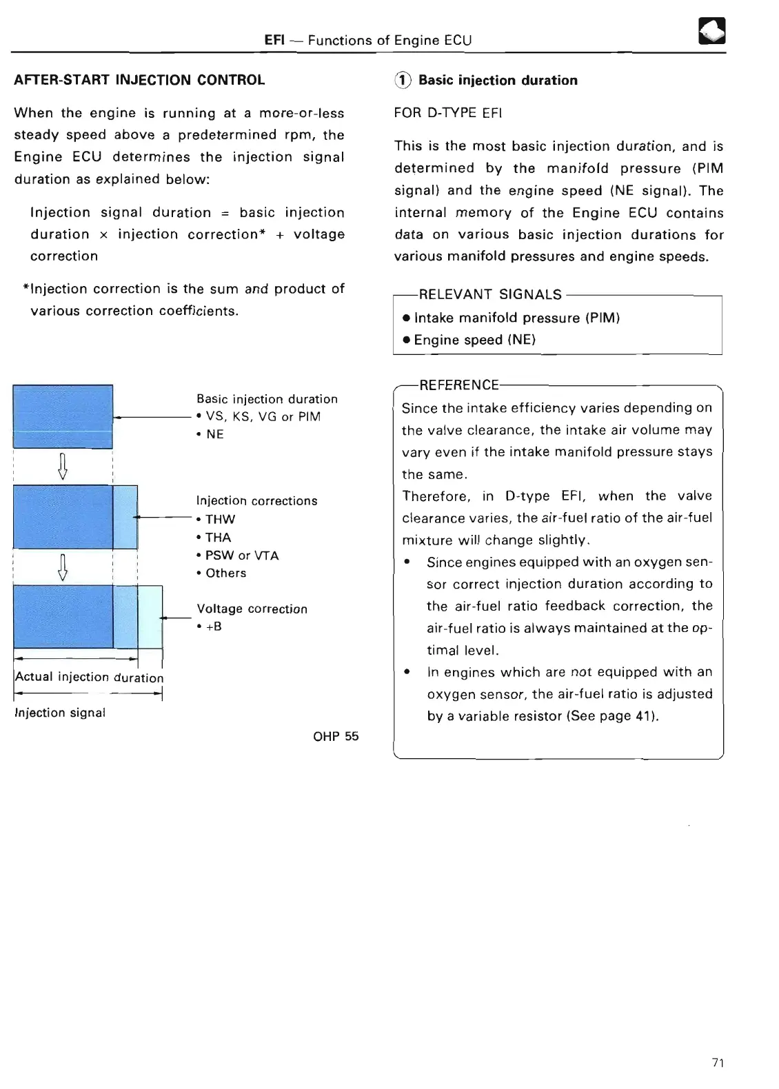
Injection signal duration = basic injection
duration x injection correction* + voltage
correctio
n
*Injection correction is the sum and product of
various correction coefficients
.
Basic injection duration
• VS, KS, VG or PI
M
• N
E
Injection corrections
• TH
W
• TH
A
• PSW or VTA
• Other
s
Voltage correction
• +
B
Actual injection duratio
n
Injection signal
OHP 55
1 Basic injection duratio
n
FOR D-TYPE EF
I
This is the most basic injection duration, and is
determined by the manifold pressure (PIM
signal) and the engine speed (NE signal)
. The
internal memory of the Engine ECU contains
data on various basic injection durations for
various manifold pressures and engine speeds
.
-RELEVANT SIGNAL
S
• Intake manifold pressure (PIM)
• Engine speed (NE
)
REFERENCE
Since the intake efficiency varies depending on
the valve clearance, the intake air volume may
vary even if the intake manifold pressure stays
the same
.
Therefore, in D-type EFI, when the valve
clearance varies, the air-fuel ratio of the air-fuel
mixture will change slightly
.
• Since engines equipped with an oxygen sen-
sor correct injection duration according to
the air-fuel ratio feedback correction, the
air-fuel ratio is always maintained at the op-
timal level
.
• In engines which are not equipped with an
oxygen sensor, the air-fuel ratio is adjusted
by a variable resistor (See page 41)
.
71