06
2. Connection and Installation
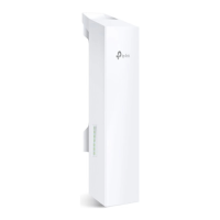
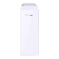
Connect and mount the CPE and power adapter as shown below. The
IROORZLQJLQWURGXFWLRQWDNHV&3(DVDQH[DPSOH
r&RQQHFWLQJ&3(DQG3RZHU$GDSWHU
&RQQHFWWKH&3(DQGSRZHUDGDSWHUDVVKRZQLQWKHƮJXUHEHORZ
Ethernet cable length up to 60m
You should prepare an adequate
Ethernet cable to connect the CPE
and the passive PoE adapter.
Shielded CAT5e (or above) cable
with ground wire is recommended
(refer to the next section).
Connect to a computer,
router or switch.
(Depending on your
intended usage and/or
network topology.)
Slide to replace the cover
of the CPE when all
FRQQHFWLRQVDUHƮQLVKHG
LAN0
PoE
LAN