5
6
TL-SG1008/TL-SG1016/TL-SG1024
Gigabit Ethernet Switch User's Guide
TL-SG1008/TL-SG1016/TL-SG1024
Gigabit Ethernet Switch User's Guide
2) The Power indicator will light up.
If the LED indicators don’t respond as described above, please check the
power supply and connection.
Chapter 3: Identifying External Components
This Chapter describes the front panel, rear panel and LED indicators of the
Switch. TL-SG1008, TL-SG1016 and TL-SG1024 just differ in the number of
LED indicators and ports and all figures in this guide are of TL-SG1024.
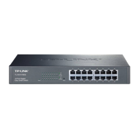
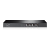
3.1 Front Panel
The front panel of the TL-SG1024 consists of switch LED indicators, 24
10/100/1000Mbps RJ-45 ports.
Figure 3-1 TL-SG1024 Switch Front Panel sketch
3.2 Rear Panel
The rear panel of the TL-SG1024 only features a power receptacle, which is
an AC power receptacle. Connect the female of the power cord head here,
and the male head to the AC power outlet.
Figure 3-2 TL-SG1024 Switch Rear Panel sketch
3.3 LED Indicators
The LED indicators include Power, 1000Mbps Link/Act and 10/100Mbps
Link/Act LED indicators, which are used for monitoring and pre-
troubleshooting of the Switch. The following section shows the LED indicators
for the switch along with an explanation of each indicator.
Figure 3-3 TL-SG1024 Switch LEDs sketch
× Power LED: This indicator will light solid red when the Switch powers
up. If the LED is not lit, please check the power supply and connection.
× 1000Mbps Link/Act LED: This indicator will light solid green when the
corresponding port is connected to a 1000Mbps device and will flash
green when data is being transmitted or received on the working
connection.
× 10/100Mbps Link/Act LED: This indicator will light solid green when
the corresponding port is connected to a 10/100Mbps device and will
flash green when data is being transmitted or received on the working
connection.
100-240V~ 50-60Hz 0.6A