BLUE M
Blue M - - DC 146 Series Industrial Ovens, Models DC, DCW, DCI, DCC
Page 43
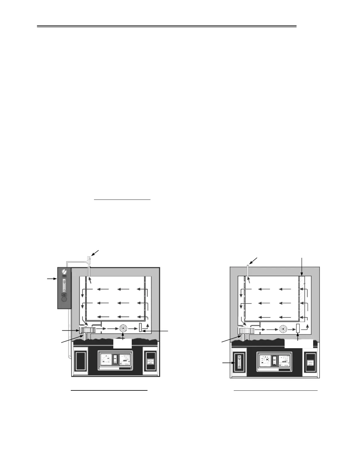
CLEAN ROOM MODEL AIR FLOW
INERT GAS MODEL AIR FLOW
6.4 Airflow Description for Models DCI and DCC
In the Model DCI and DCC ovens, inert gas is injected into the conditioning plenum below the inlet of the
blower wheel. The gas mixes with circulating process air and is forced through the heaters and the water-
cooled cooling coil, and is discharged up into the right side duct wall.
Conditioned air enters the workspace through either pierced or semi-pierced openings over the entire height
and depth of the workspace. The air flows in a horizontal pattern from right to left to condition the product,
and exits through pierced openings in the left side duct wall. Process air returns to the conditioning plenum
and the cycle continues.
In the Model DCC only, the air will pass through a HEPA / ULPA filter before entering the workspace.
Chamber Venting:
To insure than an overpressure condition does not develop within the chamber, a vent port is installed in the
chamber ceiling. For the Model DCI, a Pressure Relief Valve PRV is installed on the vent port atop the
chamber. PRV will automatically open when chamber pressure reaches 0.5 PSI. Slight chamber pressures
up to 0.5 PSI will not adversely affect the integrity of the oven door seal.
For the Model DCC, a PRV is not installed on the vent port. It is left open to vent continuously.
6.4.1 Model DCI & DCC Airflow Diagrams
Cooling Coil
Pressure Relief Valve
Vent Port
Gas
Control
Panel
Flowmeter
Inert Gas Inlet
Inert Gas Inlet
HEPA Filter
Heater
Blower Wheel
Coolin
Coil


 To Next Page