BLUE M
Blue M - - DC 146 Series Industrial Ovens, Models DC, DCW, DCI, DCC
Page 46
7.1 Model DCI Gas Control System
An inert gas sytem is used to maintain an inert atmosphere in the oven at a slight positive pressure during
the entire process cycle. The oven is initially purged of atmospheric air for a specific time period before
heating is allowed to begin. A constant flow of inert gas is then maintained during the heating and cooling
cycles. Inert gas flow and chamber pressure are monitored and regulated with various instruments on the
front control panel. The gas is injected into the chamber through a small port located beneath the blower
wheel in the conditioning plenum.
The following inert gases are approved for this oven.
• Argon
• Carbon Dioxide
• Helium
• Nitrogen
Warning! This oven is designed for use with only non-explosive, non-flammable, inert gases.
Operator injury and equipment damage may result if all safety precautions are not followed.
Initial Chamber Purge Cycle:
Before the process cycle is allowed to begin, a chamber purge cycle is initiated which lasts for a set amount
of time dependent on oven size and purge rate. These values are listed in the Gas Flow Rate Table below.
The purge cycle is designed to purge the chamber of existing atmospheric air in the chamber and replace it
with an inert gas. All oxygen, water vapor, airborne contaminants, etc., are removed.
We recommend that a volume of inert gas at least 5 to 10 times the volume of the work chamber be forced
through the oven. The Gas Flow Rate Table reflects a rate of approximately 7 times the volume for the
chamber listed.
The Purge Rate Adjustment needle valve on the flowmeter is used to adjust gas flow during the Purge Cycle.
This would also be the maximum flow allowed. Please note that your process may require a slight variation.
Important! Make sure the Purge Flow Rate is maintained during each purge cycle.
7.0 INERT GAS CONTROL SYSTEMS
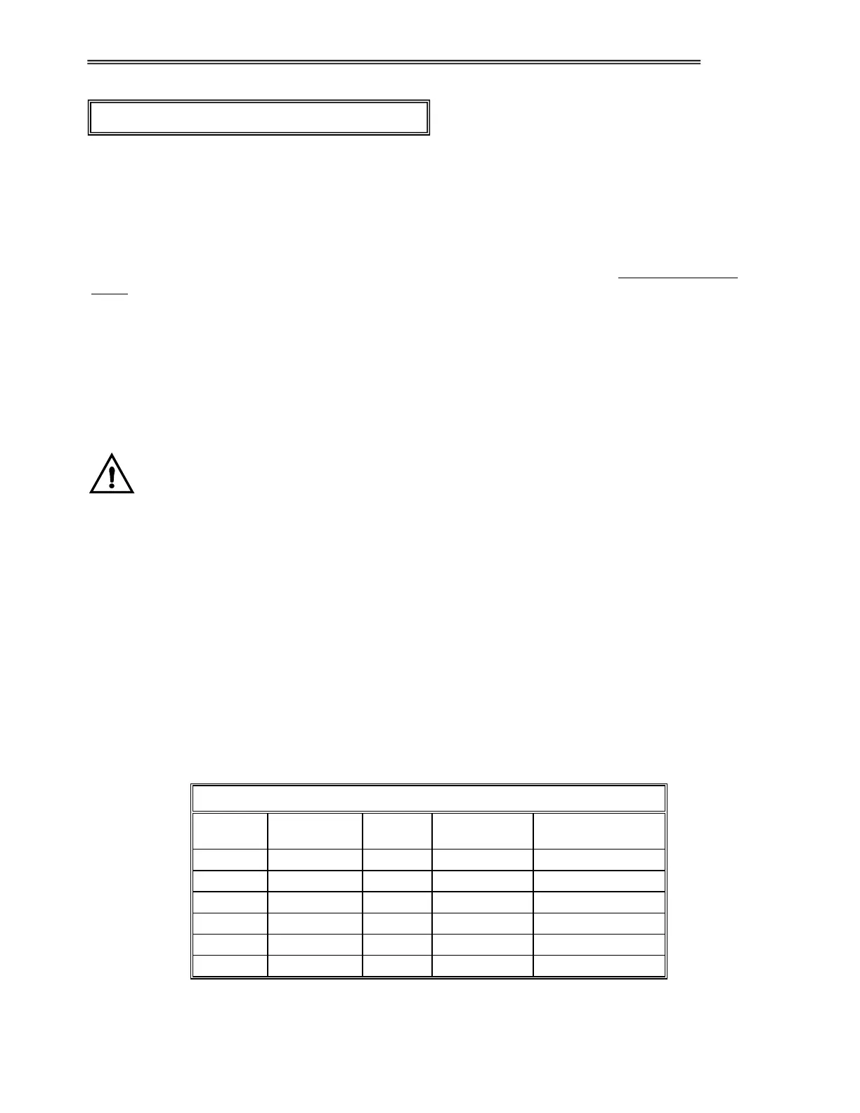
Gas Flow Rate Table
MODEL
PURGE
FLOW RATE
PURGE
TIME
RUN FLOW
RATE
COOL DOWN
FLOW RATE
DCI -146 100 SCFH 11 min. 20 SCFH Same as Run Rate
DCI -206 100 SCFH 27 min. 25 SCFH Same as Run Rate
DCI -256 200 SCFH 18 min. 30 SCFH Same as Run Rate
DCI -136 200 SCFH 30 min. 60 SCFH Same as Run Rate
DCI -336 200 SCFH 30 min. 60 SCFH Same as Run Rate
DCI -1406 600 SCFH 25 min. 120 SCFH Same as Run Rate
 Loading...