©1999 Trace Engineering
Battery Wiring
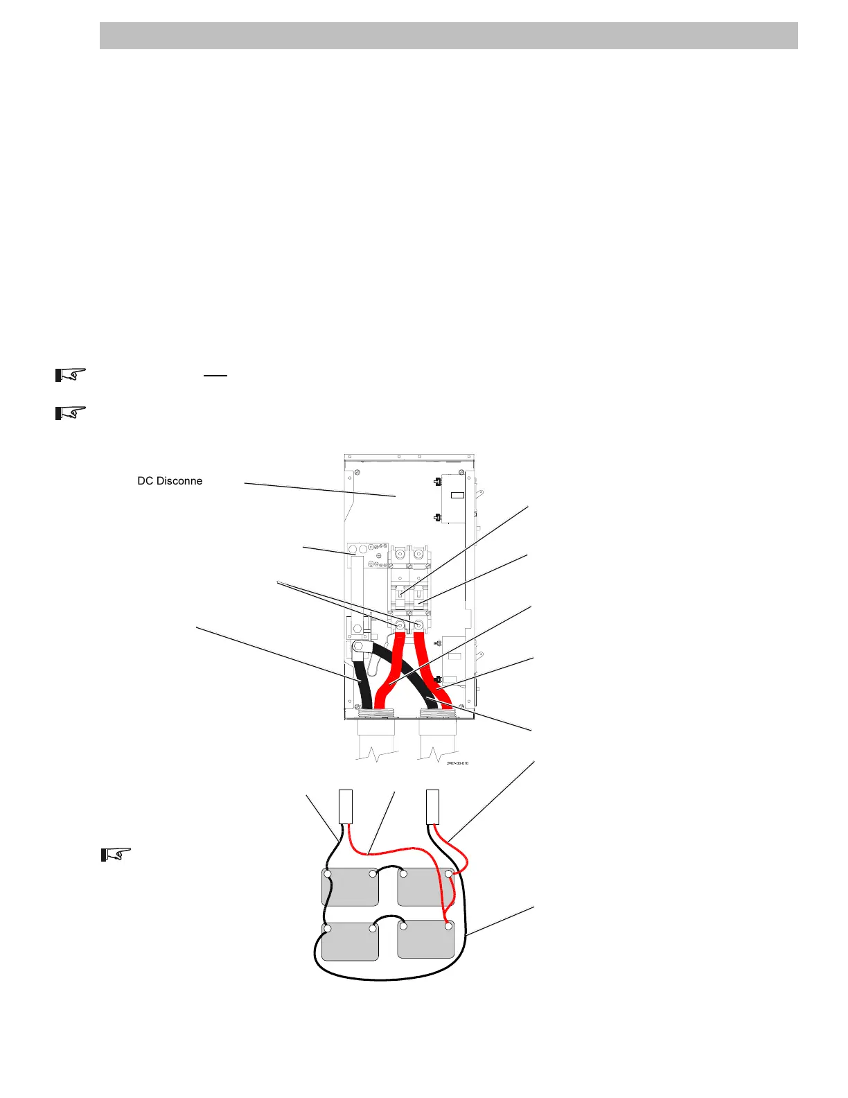
Route the battery cables through the conduit to the DC Disconnect Box. Use a minimum of #4/0 AWG
wire for a 250 amp battery disconnect breaker (or #2/0 AWG for a 175 amp battery disconnect breaker).
Smaller diameter wire results in poor inverter performance and the risk of fire due to the wires overheating.
Connect the Negative wires to the negative grounding bond block and tighten connections.
Connect a Positive wire to one of the lower terminals on the Battery Disconnect breaker.
Connect the other Positive wire to the lower terminal on the second Battery Disconnect breaker.
Torque Battery breaker connections to 275 in-lb (23 ft-lb), (31 N-m). Refer to battery manufacturers
specifications for battery terminal torque specifications.
After torquing, coat the battery connections with petroleum jelly or other anticorrosion grease designed
for battery terminals. Do not put any anticorrosion grease between the terminals and the battery cable.
NOTE: Use only
one battery bank for both inverters. Refer to Figure 12 for an example of a battery hookup.
NOTE: Refer to the inverters Operators manual for more detailed examples of battery hookups (i.e., 12 V,
24 V and 48 V).
Figure 12
Battery Wiring (24 v dc System)
2.0 INSTALLATION
11
DISCONNECT
BATTERY
OFF
ON
OFF
ON
ARRAY
SOLAR
SOLAR
ARRAY
ARRAY
SOLAR
DC Disconnect Box
Battery Disconnect 1 Breaker
(DR system shown)
(Disconnect 2 on SW Systems)
Battery Disconnect 2 Breaker
(DR system shown)
(Disconnect 1 on SW Systems)
Negative 1
Negative Grounding Bond Block
(On opposite side on SW
installations)
Positive 1
Positive 2
Negative 2
–
– + – +
+–
+
CONDUIT FOR
INVERTER 2
CONDUIT FOR
INVERTER 1
2903-00-021
12 Volt
Battery
12 Volt
Battery
12 Volt
Battery
12 Volt
Battery
Positive 1
Positive 2
Negative 1
Negative 2
NOTE: Connect each inverter at
opposite ends of the battery
bank. This balances the current
flowing through the entire bank
and provides an equal charge/
discharge through all of the
batteries.
Torque to 275 in-lb (23 ft-lb)