©1999 Trace Engineering
NEUTRAL NOT BONDED TO GROUND
RED#6AWG
WHITE #6AWG
INV 1
INV 2
D
OFF
60
D
OFF OFF
D
60
D
OFF
6060
0N0N
SOURCE AN D LOA D
INPUT AND OUTPUT
NEUTRAL
GROUND
2903-00-027
Inverter 1
HOT IN L1
(Center ac breaker)
Inverter 1
HOT OUT
L1
(Top ac breaker)
*Inverter 2 (Bottom ac breaker)
*Inverter 2
HOT IN L2
(Center ac breaker)
*Inverter 2
HOT OUT L2
(Top ac breaker)
Inverter 1 (Bottom ac breaker)
Ground Block
Neutral Block
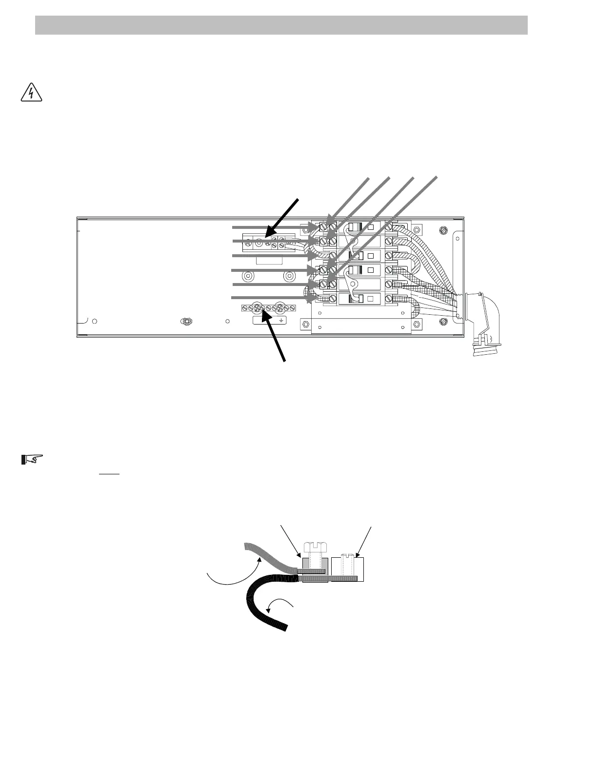
Service Crimps are provided to allow utility
and load connections. DO NOT REMOVE
FACTORY INSTALLED WIRING!
Figure 18
DR Series AC Disconnect Component Identification
AC WiringDR Series Dual Inverter Models
WARNING: THIS SECTION DEALS WITH WIRING THE MAIN SERVICE UTILITY PANEL TO THE POWER
PANEL. ENSURE THAT ALL AC POWER TO THE UTILITY PANEL IS SWITCHED OFF.
Figure 19
Breaker Terminal Lug Detail (side view)
NOTE: Service Crimps, provided on the breaker terminals, are for external input (utility) and output (load)
wiring. Do NOT remove existing factory wiring or screws.
Breaker Lug
Service Crimp
Existing Factory Wiring
Added Input or
Output Wire
2906-00-026A
16
2.0 INSTALLATION