©1999 Trace Engineering
Mounting:
NOTE: The mounting recommendations and instructions contained in this section have been developed to
meet seismic code requirements according to the 1997 Uniform Building Code for all seismic regions within
the United States. This applies to light wood framed structures such as those commonly found in residential
construction. If the Power Panel is to be mounted to a structure that is not a residential-type wood framed
wall, and/or the mounting wall supports more than one floor and one roof simultaneously, or if the structure is
classified as a commercial or industrial building, contact the local building inspector for further information
before proceeding with this installation.
The Power Panel can be installed on either a load bearing or non-load bearing wall. Depending upon the
Power Panels components, it can weigh as much as 400 lbs (182 kg). A 4' x 8' x 3/4" sheet of plywood (floor
to ceiling) is recommended to provide additional wall strength. The plywood backing is required for Power
Panels weighing more than 300 lbs (136 kg) installed on load bearing walls.
Procedure
1. Locate the studs in the wall (either 16" or 24" on center) and mark their locations.
2. If plywood is used, apply adhesive to the back and center it on the wall. Secure it into the studs and
around the perimeter using #12 wood screws on 6" spacing. Counter sink the screws. Paint the plywood
to match the surrounding wall color if desired.
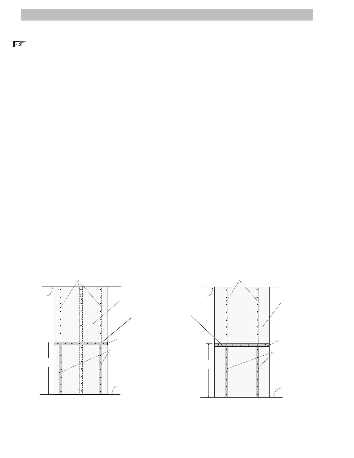
3. Using 2 x 4's, build a frame for holding the Power Panel in place while it is being secured. The top of the
frame should be approximately 3-1/2 to 4 feet from the floor. Use 3" x 1/4" lag bolts (on 6" centers) to
mount the 2 x 4. Keep all screws at least 3/4" away from the top of the horizontal 2 x 4 to allow the bottom
flange of the Power Panel to slip behind it. See Figures 2 and 3.
4. Drill pilot holes according to the dimensions in Figure 4.
5. With the help of a friend, lift the Power Panel into position. It should be centered (and level) on the
plywood. Secure the Power Panel using #10 wood screws (on 16" center) or #12 wood screws (on 24"
center) through each of the holes in the backing panel. Avoid hitting the wood screws. Screws must
penetrate 1-3/4" into the framing.
Wall studs 24 inch on
center
2 x 4 frame
4 ft. x 8 ft. x 3/4 in plywood
backing
Floor
2 x 4 support studs
Ceiling
2903-00- 003
Approximately
3-1/2–4 ft
Wall studs 16 inch on
center
2 x 4 frame
4 ft. x 8 ft. x 3/4 in plywood
backing
Floor
2 x 4 support studs
Ceiling
2903-00-003
Approximately
3-1/2–4 ft
Figure 2
Power Panel Support Structure
(16" on-center studs)
Figure 3
Power Panel Support Structure
(24" on-center studs)
2.0 INSTALLATION
4
Adjust the height of the panel so the
bypass switch is within easy reach