©1999 Trace Engineering
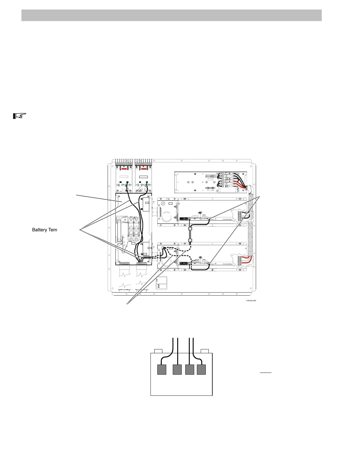
Battery Temperature Sensor Wiring (DR Models)
Battery Temperature Sensors (BTS) should be placed on the side of the battery. They transmit
temperature information to the charger and adjust the charging rate according to the battery temperature. Up
to four sensors can be connected in a dual inverter system with two charge controllers.
1. Locate the battery temperature sensors and route them down through the conduit in the DC Disconnect
Box to the batteries.
2. Place all sensors onto the side of same battery (located in the middle of the battery bank) to prevent
different charging rates based on temperature variances.
NOTE: Temperature sensor cables are already connected to the inverters and PV controllers (if ordered). The
cables only need be run through the conduit to the batteries.
Figure 11
Battery Temperature Sensor (BTS) Wiring
10
OFF
ONON
OFF
87
DEEP CYCLE LEAD ACID
POWER ON/OFF
INVERTER MODE
SEARCH MODE WATTS
OVER TEMP RED/OVERLOAD GRN
BATTERY HI RED/ BATTERY LOW GRN
CHARGE R: GRN= F LOAT/ORN B LINK =AB SO RP/O RN=B ULK
COM PO RT
0
10
>100
25
60
PbCa-MAINTENANCE FREE
GEL CE LL
3
4
5
6
AC TRANSFER THRESHOLD
BATTERY SENSE
BATTERY CHARGER RATE
BATTERY CAPACITY
OVER-DISCHARGE PROTECTION
OFF
MAX
MIN
Amp/Hrs
125
50
ON
.37K
.5K
1K
250
EQUALIZE 1
EQUALIZE 2
2
9
0
1
Batt ery Type Select or
MAX
OVER TEMP RED/OVERLOAD GRN
BATTERY HI RED/ BATTERY LOW GRN
CHARGE R: GRN= F LOAT/ORN B LINK =AB SO RP/O RN=B ULK
POWER ON/OFF
INVERTER MODE
SEARCH MODE WATTS
COM PO RT
>100
0
10
25
60
MIN .5K
BATTERY SENSE
AC TRANSFER THRESHOLD
BATTERY CAPACITY
OVER-DISCHARGE PROTECTION
.37K
ON
OFF
125
50
1K
250
Amp/Hrs
BATTERY CHARGER RATE
Batt ery Type Select or
EQUALIZE 2
EQUALIZE 1
GEL CE LL
PbCa-MAINTENANCE FREE
DEEP CYCLE
6
5
4
3
LEAD ACID 7
1
0
9
2
8
GND
NEU IN
NEU OUT
POSITIVE
NEGATIVE
POSITIVE
NEGATIVE
BAT+ PV+ BAT-PV- PV+BAT+ BAT-PV-
HOT IN
NEU IN
HOT OUT
NEU OUT
GND
NEUTRAL NOT BONDED TO GROUND
INV 1 OUTPUT
INV 1 INPUT
RED#6AWG
INVERTER 2
INVERTER 1
DISCONNECT
BATTERY
ARRAY
SOLAR
#2355
#2360
ARRAY
SOLAR
#2385
INV 1
INV 2
D
OFF
60
D
OFF OFF
D
60
D
OFF
6060
0N0N
SOURCE AND LOAD
INPUT AND OUTPUT
NEUTRAL
GROUND
PN 2355
HAZARD OF ELECTRICAL SHOCK OR BURN.
TURN OFF THE AC AND DC POWER SUPPLYING
THIS EQUIPMENT BEFORE WORKING INSIDE.
THIS SYSTEM MAY RECEIVE POWER FROM
MORE THAN ONE SOURCE. REPLACE COVER
BEFORE TURNING POWER ON.
RISQUE DE CHOCS ELECTRIQUES. NE PAS
TOUCHER LES PARTIES NON ISOLEES DU
CONNECTEUR DE SORTIE OU LES BORNES
NON ISOLEES DE L’ACCUMULATEUR. COUPER
TOUTLES LES SOURCES D’ALIMENTAT ION
AVANT D E FAIRE L’ENTRETIEN ETLES
REPAR AT ION S .
DANGER:
AVERTISSEMENT:
POWE R SU P P LIES
CAN/CSA-C22.2 No. 1 07.1-M1
COMMERCIAL AND INDUSTRIAL
SYSTEMS STANDARD UL1741
USE IN PHOTOVOLTAIC POWER
POWER CONDITIONING UNITS FOR
L
I
S
T
E
D
C
67664
CERTIFIED TO
R
TRACE ENGINEERING 5916 195TH ST NE
ARLINGTON, WA. 98223 MADE IN U.S.A.
L
S
T
I
E
D
R
SOLAR
ARRAY
Battery Temperature
Sensor wires.
BTS Connector
(front panel)
BTS wires run through the grommets in the inverter housing
and along the back of the inverter. These wires are already
installed
DC Disconnect Box
BATTERY
BATTERY TEMPERATURE SENSORS
Mount the battery temperature sensors (BTS)
to the side of the same battery (located in the
middle of the battery bank).
2.0 INSTALLATION