BM-20 PLUS Operator’s Manual 9
After setting the bevel angle, adjust the bevel width using the depth knob. The
widt
h pitch provides only a rough value as the bevel width varies with the angle.
The maximum bevel width
(b = 21 mm, 13/16’’) is obtained for 45°. The demanded
bevel width for the required angle must be determined experimentally by gradually
increasing the penetration of the milling cutters into the workpiece.
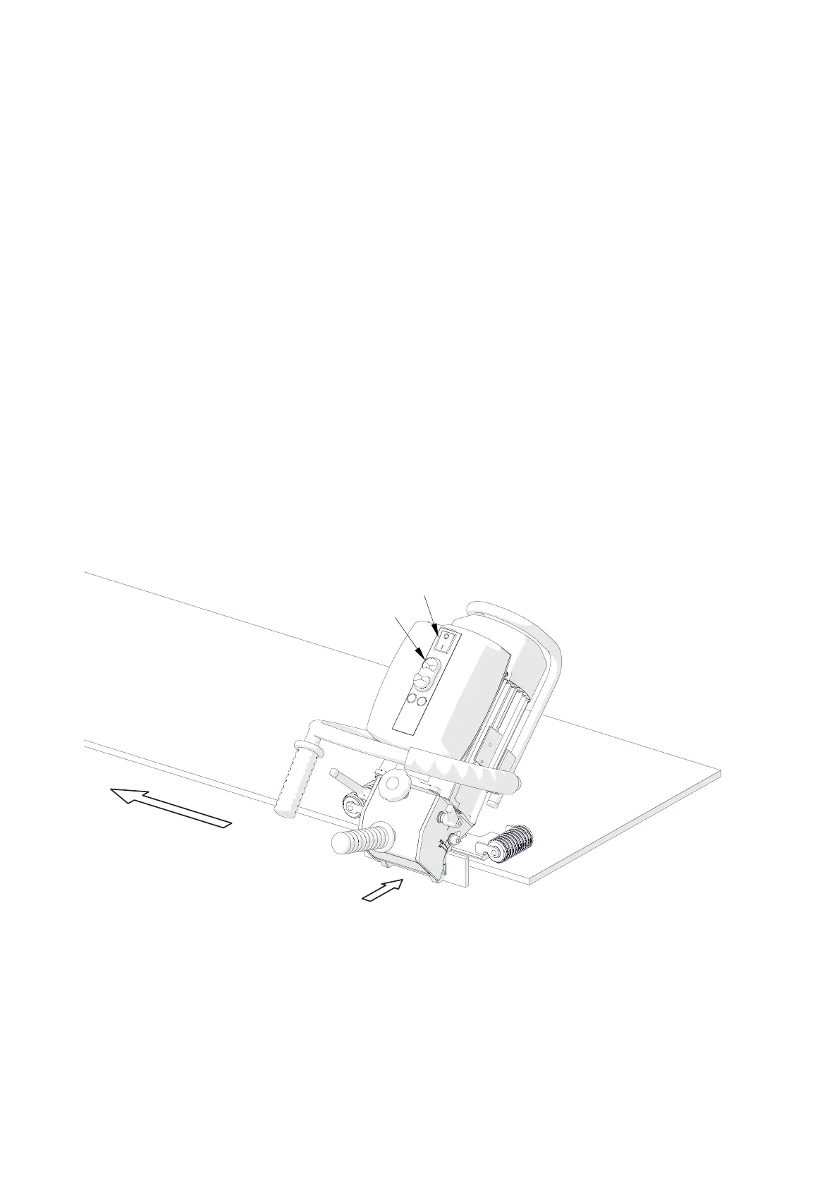
3.2. Operating
After setting the bevel angle and width, connect the machine to a properly grounded
power outlet. Then, place the machine vertically on the right side of the workpiece in
such a way to rest the rollers on the plate (Fig. 5) and maintain a gap between the
milling cutters and the plate. Next, power on the machine by toggling the power switch
to position ‘I’ and start the motor using the green START button. Slide the machine
towards the plate face and bevel by sliding the machine to the left, constantly pressing
the machine against the workpiece.
Bevelling is performed according to the counter-rotation. The rotation direction of
the milling cutters is marked on the motor disk under the milling cutters cover.
Fig. 5. Machine properly positioned on the workpiece
The feed rate will depend on the profile and composition of the workpiece.
Most steels capable of being welded can be bevelled in one pass. However,
bevels wider than 12 mm (1/2’’) should be accomplished in at least two or three passes
as this will require less effort and the process will take less total time than for bevelling
in a single pass.
Feed direction
Power switch
START
Slide towards after starting the motor