15
23 Series High Wall Unit
NOTE: The wiring diagrams in this guide are included as a reference. The manufacturer has a policy
of continuous product and product data improvement and reserves the right to change design and
specifications without notice. Always check the unit nameplate and wiring diagram for the actual unit
requirements.
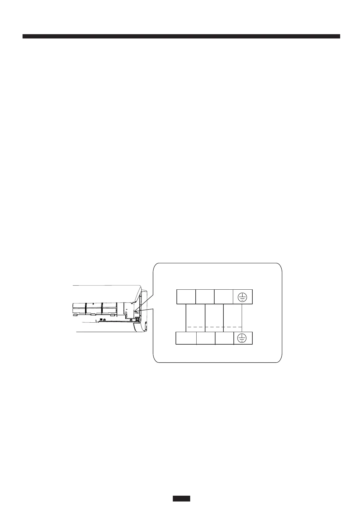
3. Remove the wire clip and connect the power connection wire to the wiring terminal according to
the correct color coding. It is recommended to use 4 wire colors (for example: Blue, Black, Red,
Green. Connect Blue to 1, Black to 2, Red to 3 and Green to Ground). All wiring shall use ring
or spade type crimped or soldered connectors (as shown in the outdoor unit installation section
or manual). Ensure electrical connections are tight and strain reliefs are in place. Regardless
of wire color used, The wire terminals labeled 1, 2, 3 and ground must be landed on the
corresponding terminal in the outdoor unit.
4. Put the wiring cover back on the unit and tighten the fastener.
5. Close the front panel.
6. The primary disconnect for both the indoor and outdoor unit shall be wired to disconnect the
branch circuit feeding the outdoor unit. The Indoor unit obtains high voltage and communication
from the outdoor unit. If the AHJ (authority having jurisdiction) requires a branch circuit
disconnect before the indoor unit, then break all three legs between the outdoor unit and indoor
unit using a switch with current ratings suitable for use with these types of systems.
7. The system must be disconnected at the outdoor unit before performing service or
maintenance to avoid risk of electric shock or damage to equipment.
8. Terminal 2 carries communication signals and should not be cut or spliced. Do not use splices
in any wire between the indoor and outdoor unit.
a) If an external drain pump with a float switch is utilized, power the drain pump from
terminals 1 and 3; the float switch should be wired to break leg 3.
b) Do not break leg 1 or leg 2 with a float switch.
9. The ground wire must connect directly from the outdoor unit to the indoor unit. To avoid
communication errors, do not connect the ground wire to the terminal block from any other
location.
Indoor Wiring Example
Outdoor unit connection
09, 12, 18, 24K models:
3
2
N(1)
green
red
black
blue
Field Wiring
3
2
N(1)
NOTE: Field wiring colors indicated in this illustration are intended as an example and may differ based on
the electrical contractor choice of wire colors.
Indoor models