20
4T-V8-SF-1M-EN
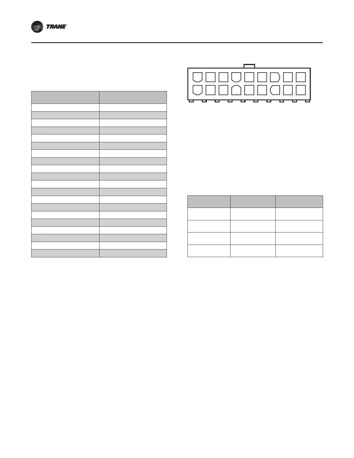
Suction Line Pressure
Transducer
This table shows the corresponding voltage and
pressure readings for the Suction Line Pressure
Transducer when measured across pins 7 and 8.
35(6685( 36,*
92/76 '&
3,1 72 3,1
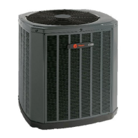
Figure 10. Suction Pressure Transducer
Pins 7 (White) & 8 (Black)
123456789
101112131415161718
A working Suction Pressure Sensor is required for the
following:
• Start Up (Pressure Limits)
• Low Pressure, Loss of Charge Protection
• Indoor Coil Freeze Protection
• Outdoor EEV Control (Target Super Heat)
• Diagnostics; Reverse Rotation, Charge Level,
Indoor/Outdoor Airflow
The Suction Pressure Transducer control is measured
across pins 7 and 8 and has an active 0–4.9VDC
transducer input for sensing low suction pressure.
'(6&5,37,21 /2&$7,21 :,5( &2/25
9'& 32:(5 3,1 5('
287387 3,1 :+,7(
&20021 3,1 %/$&.
*5281' 3,1 *5((1
SSEENNSSOORRSS