50
4T-V8-SF-1M-EN
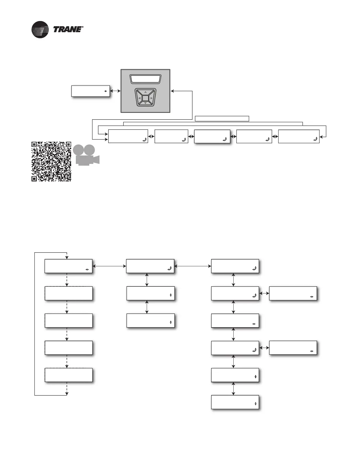
Communicating Display Assembly
TECHNICIAN MENUS
SYSTEM STATUS
XXXXXXXXXXXXXXXX
NAVIGATION
• To enter and exit Technician Menus, press the Up/Down buttons
simultaneously for 5 seconds.
• To return to the Home Screen, press the Up/Down buttons
simultaneously for 5 seconds.
• To return to the top level of any menu, press the Left/Right buttons
simultaneously for 5 seconds.
• After five minutes of inactivity in the Technician Menu section, the
Home Screen will be displayed. Pressing the Enter button for
5 seconds will increase this time to 20 minutes.
Scan t o see an
overview video
about the CDA
ALERT HISTORY
MENU
ALERT MENU
CONFIG MENU
CONTROL MENU
MONITOR MENU
The Monitor Menu
displays information
on System status,
Drive stats and the
System Tachometer.
The Alert History
menu displays alerts
stored over time. Note
that clearing Alert
History will also clear
Active Alerts.
The Alert Menu
displays active alerts.
The Configuration
Menu is where
System parameters
and options are set
and reported.
The Control Menu
contains a selection of
unit function tests that
are used to verify
operation.
Home Screen— Communicating Display Assembly
Table 2. Status Menu/Home Screen
7KH 6\VWHP 6WDWXV LV VKRZQ FRQWLQXRXVO\ RQ WKH +RPH 6FUHHQ
7KH 6\VWHP 6WDWXV ZLOO DOWHUQDWH ZLWK )DXOW ,QIRUPDWLRQ LI WKHUH LV DQ DFWLYH IDXOW
/RZ OHYHO IDXOWV GR QRW DSSHDU RQ WKH +RPH 6FUHHQ
SYSTEM STATUS (1)
Auto Scroll
Auto Scroll
XXXXXXXXXXXXXXXX
ALERT 1
<Alert short Text>
ALERT 2
<Alert short Text>
ALERT 3
<Alert short Text>
ALERT 4
<Alert short Text>
UNIT DATA
UNIT MODEL #
XXXXXXXXXXXXXXXX
UNIT SERIAL #
XXXXXXXXXXXXXXXX
UNIT CONTROLS
XXXXXXXXXXXXXXXX
AOC SW BUILD
XXXXXXXXXXXXXXXX
MOC SW VERSION
XXXXXXXXXXXXXXXX
CDA SW BUILD
XXXXXXXXXXXXXXXX
PM SW VERSION
XXX
DRV COMP SIZE
XXX
XXX
AOC SW VERSION
XXXXXXXXXXXXXXXX
CDA SW VERSION
XXXXXXXXXXXXXXXX
Note: This is compressor size in
tonnage stored in the Personality
Module expressed in 2,3,4 or 5.
NOTES:
System Status will display a value from the left column
STANDBY Idle, No demand present. If in Standby due to an alarm
and system is in soft lockout...”SOFT LOCK” will display on CDA
COOLING Compressor cooling demand
HEATING Compressor heating demand
DEFROST Compressor defrost (cooling) demand
LOAD SHED Compressor demand inhibited from external control
OIL RETURN Compressor demand imposed by protection logic
CLG DERATE Compressor demand imposed by protection logic
HTG DERATE Compressor demand imposed by protection logic
PUMP DOWN Command Compressor to operate at Maximum speed in
Cooling and Nominal speed in Heating
CHARGING Compressor cooling demand imposed by system logic
CHECK CHARGE Compressor heating demand imposed by system logic
SOFT LOCK System in a 5 or 15 minutecutout period due to an alert