4
18-BC97D1-1D-EN
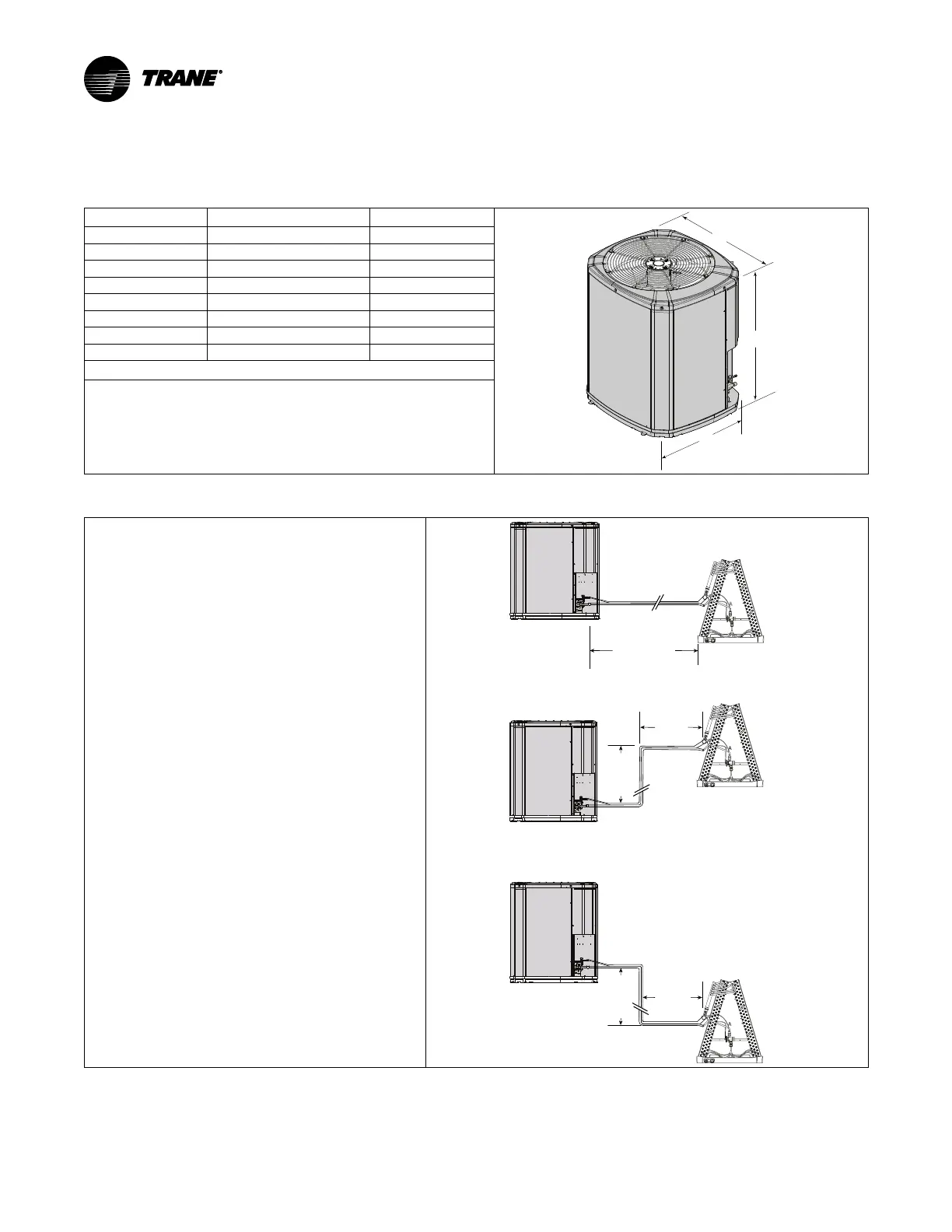
Unit Location Considerations
Table 1. Unit Dimensions and Weight
Models
H x D x W (in) Weight * (lb)
4TWA4036A3 29 x 34 x 37 208
4TWA4042A3 29 x 34 x 37 208
4TWA4048A3 33 x 34 x 37 218
4TWA4060A3 45 x 34 x 37 275
4TWA4036A4 29 x 34 x 37 216
4TWA4042A4 29 x 34 x 37 208
4TWA4048A4 33 x 34 x 37 218
4TWA4060A4 45 x 34 x 37 274
* Weight values are estimated (uncrated).
• When mounting the outdoor unit on a roof, be sure the roof will
support the unit’s weight.
• Properly selected isolation is recommended to alleviate sound or
vibration transmission to the building structure.
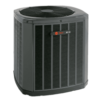
Table 2. Refrigerant Line and Service Valve Connection Sizes
1. The maximum TOTAL length of refrigerant lines from
outdoor to indoor unit should NOT exceed 150 feet
(including lift).
2. The maximum vertical change should not exceed 50
feet.
3. Service valve connection diameters are shown in the
Refrigerant line and Service Valve connection size table
on page 7.
Note: For other line lengths, Refer to Refrigerant Piping
Application Guide, SS-APG006–EN or Refrigerant
Piping Software Program, 32–3312–03 (or latest
version).
50’
Ma
x
Line
Lift
Standard
Line Set
150’ Max
Line Length
50
Max
Line
Lift
100’
M
ax
Line
Length
100’ Max
Line
Length
Refer to (a), (b), and (c) footnotes for
specific model details