84
SCXF-SVX01T-EN
sound and gas-tight connection.
9. Visually inspect the connection after brazing to locate
any pinholes or crevices in the joint. Use a mirror if joint
locations are difficult to see.
System Evacuation Procedures
• Each refrigeration circuit must be evacuated before the
unit can be charged and started.
• Use a rotary type vacuum pump capable of pulling a
vacuum of 100 microns or less.
• Verify that the unit disconnect switch and the system
control circuit switches are “OFF”.
• Oil in the vacuum pump should be changed each time
the pump is used with high quality vacuum pump oil.
Before using any oil, check the oil container for
discoloration, which usually indicates moisture in the oil
and/or water droplets. Moisture in the oil adds to what
the pump has to remove from the system, making the
pump inefficient.
• When connecting vacuum pump to refrigeration
system, it is important to manifold vacuum pump to
both high and low side of system (liquid line access
valve and suction line access valve). Follow pump
manufacturer’s directions for proper methods of using
vacuum pump.
• Lines used to connect the pump to the system should
be copper and of the largest diameter that can
practically be used. Using larger line sizes with
minimum flow resistance can significantly reduce
evacuation time.
• Rubber or synthetic hoses are not recommended for
system evacuation. They have moisture absorbing
characteristics that result in excessive rates of
evaporation, causing pressure rise during standing
vacuum test. This makes it impossible to determine if
system has a leak, excessive residual moisture, or
continual or high rate of pressure increase due to
hoses.
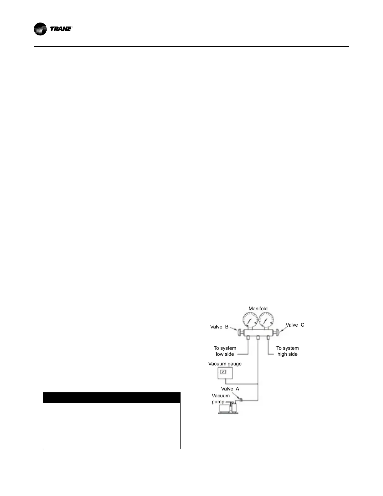
• Install an electronic micron vacuum gauge in the
common line ahead of the vacuum pump shutoff valve,
as shown in Figure 45, p. 84. Close Valves B and C,
and open Valve A.
• Start vacuum pump. After several minutes the gauge
reading will indicate the maximum vacuum the pump is
capable of pulling. Rotary pumps should produce
vacuums of 100 microns or less.
NOTICE
Motor Winding Damage!
Failure to follow instructions below could result in
compressor motor winding damage.
Do not use a megohm meter or apply voltage
greater than 50 VDC to a compressor motor
winding while it is under a deep vacuum.
• Open Valves B and C. Evacuate system to a pressure
of 300 microns or less. As vacuum is being pulled on
system, it may appear that no further vacuum is being
obtained, yet pressure is high. It is recommended
during evacuation process to “break” vacuum to
facilitate evacuation.
• To break the vacuum, shut valves A, B, and C and
connect a refrigerant cylinder to charging port on
manifold. Purge air from hose. Raise standing vacuum
pressure in system to “zero” (0 psig) gauge pressure.
Repeat process two or three times during evacuation.
Note: It is unlawful to release refrigerant into the
atmosphere. When service procedures require
working with refrigerants, the service technician
must comply with all Federal, State, and local
laws.
Standing Vacuum Test
Once 300 microns or less is obtained, close valve A and
leave valves B and C open to allow the vacuum gauge to
read the actual system pressure. Let system equalize for
approximately 15 minutes. This is referred to as a “standing
vacuum test” where time versus pressure rise. Maximum
allowable rise over a 15 minute period is 200 microns. If
pressure rise is greater than 200 microns but levels off to a
constant value, excessive moisture is present. If pressure
steadily continues to rise, a leak is indicated. Figure 46, p.
85 illustrates three possible results of “standing vacuum
test”.
If a leak is encountered, repair the system and repeat the
evacuation process until the recommended vacuum is
obtained. Once the system has been evacuated, break the
vacuum with refrigerant and complete the remaining Pre-
Start procedures before starting the unit.
Figure 45. Typical vacuum pump hookup
Maintenance
 Loading...