Page 23
Installer’s Guide
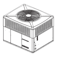
Contactor
Unit Ground Lug
Figure 24. Power Connections
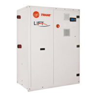
Figure 23. Power Wiring
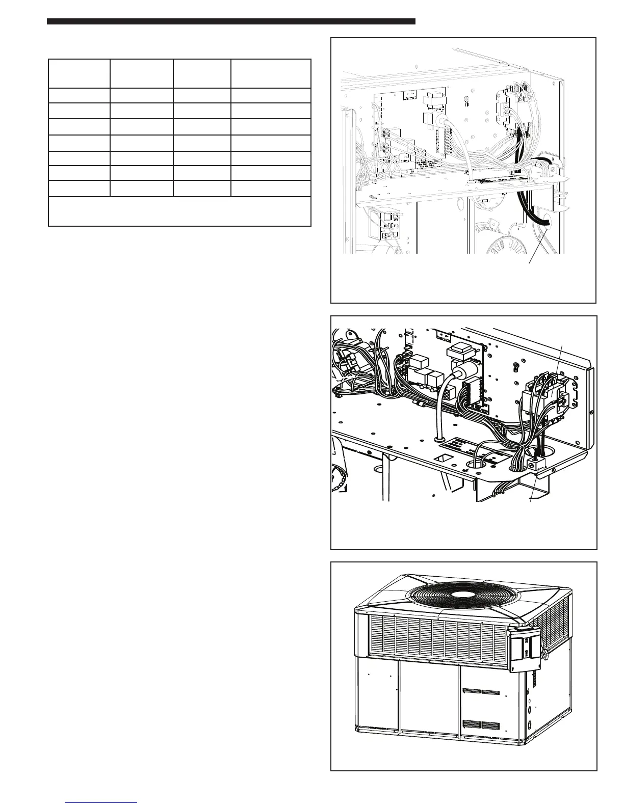
Figure 25. Mounted Disconnect Location
Run power supply Lines through weather-tight
conduit and secure to unit with strain relief
Electrical Connections
Electrical wiring and grounding must be installed in accordance
with local codes or, in the absence of local codes, with the National
Electrical Code ANSI/NFPA 70, Latest Revision.
Electrical Power
It is important that proper electrical power be available for the unit.
Voltage variation should remain within the limits stamped on the
unit nameplate.
Disconnect Switch
Provide an approved weatherproof disconnect within close proxim-
ity and within sight of the unit. If disconnect must be mounted
to the cabinet, the location shown in Figure 25 should be the only
one considered.
Over Current Protection
The branch circuit feeding the unit must be protected as shown on
the unit's rating plate.
Power Wiring
The power supply lines must be run in weather-tight conduit to the
disconnect and into the side of the unit control box. Provide strain
relief for all conduit with suitable connectors.
Provide flexible conduit supports whenever vibration transmission
may cause a noise problem within the building structure.
1. Remove the Control/Heat access panel. Pass the power
wires through the Power Entry hole in the end of the unit.
See Figure 23.
2. Connect the high voltage wires to the appropriate contactor
terminals. Single phase units use a two (2) pole contactor
and three phase units use three (3) pole contactor. Connect
the ground to the ground lug on the chassis. See Figure 25.
Be sure all connections are tight.
GROUNDING: THE UNIT MUST BE ELECTRICALLY
GROUNDED IN ACCORDANCE WITH LOCAL CODES OR
THE NATIONAL ELECTRIC CODE.
Electrical Wiring
Note: This unit is factory wired for 230V. See wiring diagram
for 208V conversion.
Table 1. Filter Sizes (field supplied filter rack)
UNIT NOMINAL CFM
FILTER SIZE
(Sq Ft)
FILTER RESISTANCE
("W.C.)
WC~3018 600 2.00 0.08
WC~3024 800 2.67 0.08
WC~3030 1000 3.33 0.08
WC~3036 1200 4.00 0.08
WC~3042 1400 4.67 0.08
WC~3048 1600 5.33 0.08
WC~3060 2000 6.67 0.08
*Filters must be installed in the return air system. The above square footages are
based on 300 F.P.M. face velocity. If permanent filters are used, size per manu-
facturer recommendation with clear resistance of 0.05" W.C.
 Loading...