Page 3
Installer’s Guide
Introduction
Contents
Safety Considerations 2
Introduction 3
Step 1-Inspect Shipment 3
Step 2-Determine Unit Clearances 4
Step 3-Review Location & Recommendation
Information 16
Step 4-Unit Installation 17
Ground Level Installation 17
Rooftop Installation -- Curb Mounting 17
Covert Horizontal Airflow to Down Airflow 17
Install Full Perimeter Roof Mounting Curb 17
Lifting and Rigging 18
Placing the Unit on the Mounting Curb 18
Rooftop Installation -- Frame Mounting 19
Rooftop Installation -- No Curb/Frame 19
Ductwork Installation 22
Attaching Downflow Ductwork to Roof Curb 22
Attaching Horizontal Ductwork to Unit 22
Condensate Drain Piping 22
Air Filter Installation 22
Electrical Wiring 23
Electrical Connections 23
Electrical Power 23
Disconnect Switch 23
Overcurrent Protection 23
Power Wiring 23
Field Wiring Diagram 24
Control Wiring (Class II) 25
Step 5-Unit Startup 25
Pre-start Quick Checklist 25
Starting the Unit in the Cooling Mode 25
Operating Pressures 25
Voltage Check 25
Cooling Shut Down 25
Starting the Unit in Heating Mode 26
Heating Shutdown 26
Sequence of Operation 26
Demand Defrost Operation 26
Defrost Control 26
Final Installation Checklist 27
Maintenance 27
Owner Maintenance 27
Service Maintenance 27
Cooling Season 27
Heating Season 27
Indoor Fan Motor Speed Tap Setting 27
Read this manual carefully before attempting to install, oper-
ate, or perform maintenance on this unit. Installation and
maintenance should be performed by qualified service techni-
cians only. This unit is listed by Underwriters Laboratory.
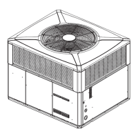
Model 2/4WC*3 heat pump units are designed for outdoor
mounting with a vertical condenser discharge. They can be
located either at ground level or on a roof in accordance with
local codes. Each unit contains an operating charge of refrig-
erant as shipped.
Extreme mounting kits are available for slab (BAYEX-
MK003A), utility curb (BAYEXMK002B) and perimeter curb
(BAYEXMK001A) mountings.
This guide is organized as follows:
Step 1 - Inspect Shipment
Step 2 - Determine Unit Clearances
Step 3 - Review Location & Recommendation Information
Step 4 - Unit Installation
Step 5 - Unit Startup
Sequence of Operation
Maintenance
Step 1—Inspect Shipment
1. Check for damage after the unit is unloaded. Report promptly
to the carrier any damage found to the unit. Do not drop the
unit.
IMPORTANT: To prevent damage to the sides and top of the
unit when hoisting, retain the top shipping skid on the unit or
use “spreader bars” as shown on page 20.
2. Check the unit’s nameplate to determine if the unit is cor-
rect for the intended application. The power supply must be
adequate for both the unit and all accessories.
3. Check to be sure the refrigerant charge has been retained
during shipment. Remove the Compressor access panel to
access the 1/4" flare pressure taps.
4. If this unit is being installed on a curb, verify that the correct
curb is provided with the unit.
• 4WC*3018-036 use model BAYCURB050A.
• 4WC*3042-060 use model BAYCURB051A.
5. If the unit is being hoisted, accessory kit BAYLIFT002A is
recommended. It includes a kit of four (4) lifting lugs and
instructions.
NOTE: If practical, install any internal accessories to the
unit at the shop.