Home
Trane
Heat Pump
4TTR3018H
Page 26 (Section 17. Wiring Diagrams)
Trane 4TTR3018H - Section 17. Wiring Diagrams
38 pages
Manual
To Next Page
To Next Page
To Previous Page
To Previous Page
Loading...
26
18-A
C79D1-10D-EN
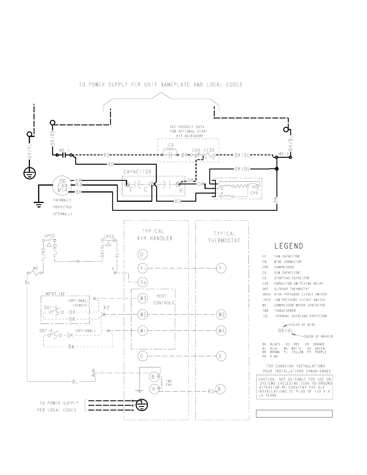
Section 17. Wiring Diagrams
PRINTED FROM D157362P05 REVB
018N, 030N, 036N, 042N & 048N Models
018H, 024H, 043A & 049A Models
25
27
Table of Contents
Main Page
Table of Contents
1
Section 1. Safety
2
Section 2. Unit Location Considerations
3
Section 3. Unit Preparation
5
Section 4. Setting the Unit
5
Section 5. Refrigerant Line Considerations
6
Section 6. Refrigerant Line Routing
8
Section 7. Refrigerant Line Brazing
9
Section 8. Refrigerant Line Leak Check
11
Section 9. Evacuation
12
Section 10. Service Valves
12
Section 11. Electrical - Low Voltage
13
Section 12. Electrical - High Voltage
15
Section 13. Start up
16
Section 14. System Charge Adjustment
17
Section 15. Checkout Procedures
23
Section 16. Refrigerant Circuits
24
Section 17. Wiring Diagrams
26
Section 18. Pressure Curves
34
Related product manuals
Trane 4TTR3030N
38 pages
Trane 4TTR3060N
38 pages
4TTR5, 4TTR4, 4TTR3, 2TTR3, 4TWR5, 4TWR4, 4TWR3, 2TWR3
8 pages
Trane 4TTR6024N
44 pages
Trane 4TTR4042N
22 pages
Trane 4TTR4018N
22 pages
Trane 4TTR5060N
28 pages
Trane 4TTR5030N
28 pages
Trane 4TTR6048N
44 pages
Trane 4TTR7 Series
24 pages
Trane 4TTR5018-060
22 pages
Trane 4TTR4A Series
8 pages