|nsta||er's Guide
MUST BE REPLACED to prevent leaks. Replace valve
stem cap and pressure tap cap finger tight, then tighten
an additional 1/6 turn. See Figures 4 and 5.
If refrigerant lines are longer than fifteen (15) feet and/or
a different size than recommended, it will be necessary
to adjust system refrigerant charge upon completion of
installation. See page 6 or the unit Service Facts.
E. ELECTRICAL CONNECTIONS
When installing or servicing this equipment, ALWAYS
exercise basic safety precautions to avoid the possibility of
electric shock.
1. Power wiring and grounding of equipment must comply
with local codes.
2. Power supply must agree with equipment nameplate.
3. Install a separate disconnect switch at the outdoor unit.
4. Ground the outdoor unit per local code requirements.
5. Provide flexible electrical conduit whenever vibration
transmission may create a noise problem within the
structure.
6. The use of color coded low voltage wire is recommended
to simplify connections between the outdoor unit, the
thermostat and the indoor unit.
Table 1 -- NEC Class II Control Wiring
24 VOLTS
WIRE SIZE MAX. WIRE LENGTH
18 AWG 150 FT
16 AWG 225 FT.
14 AWG 300 FT.
8. Mount the indoor thermostat in accordance with instruc-
tion included with the thermostat. Wire per appropriate
hook-up diagram (included in these instructions).
F. COMPRESSOR START-UP
After all electrical wiring is complete, SET THE THERMO-
STAT SYSTEM SWITCH IN THE OFF POSITION SO
COMPRESSOR WILL NOT RUN, and apply power by
closing the system main disconnect switch. This will activate
the compressor sump heat (where used). Do not change the
Thermostat System Switch until power has been applied for
one (1) hour. Following this procedure will prevent potential
compressor overload trip at the initial start-up.
G. OPERATIONAL AND
CHECKOUT PROCEDURES
Final phases of this installation are the unit Operational and
Checkout Procedures which are found in this instruction (see
table below and pages 6 and 8). To obtain proper perfor-
mance, all units must be operated and charge adjustments
made in accordance with procedures found on page 6 and in
the Service Facts.
IMPORTANT:
Perform a final un# inspection to be sure that factory tubing has
not shifted during shipment. Adjust tubing ff necessary so tubes
do not rub against each other when the unit runs. Also be sure
that wiring connections are tight and wire routing is secure.
H. SEACOAST SHIELD
Units installed -within one (1) mile of salt water, including
seacoasts and inland waterways, require the addition of
BAYSEAC001 (Seacoast Kit) at the time of installation.
IMPORTANT:
See Limited Warranty information in Use and Care Manual
7. Table i defines maximum total length of low voltage
wiring from outdoor unit, to indoor unit, _md to thermostat.
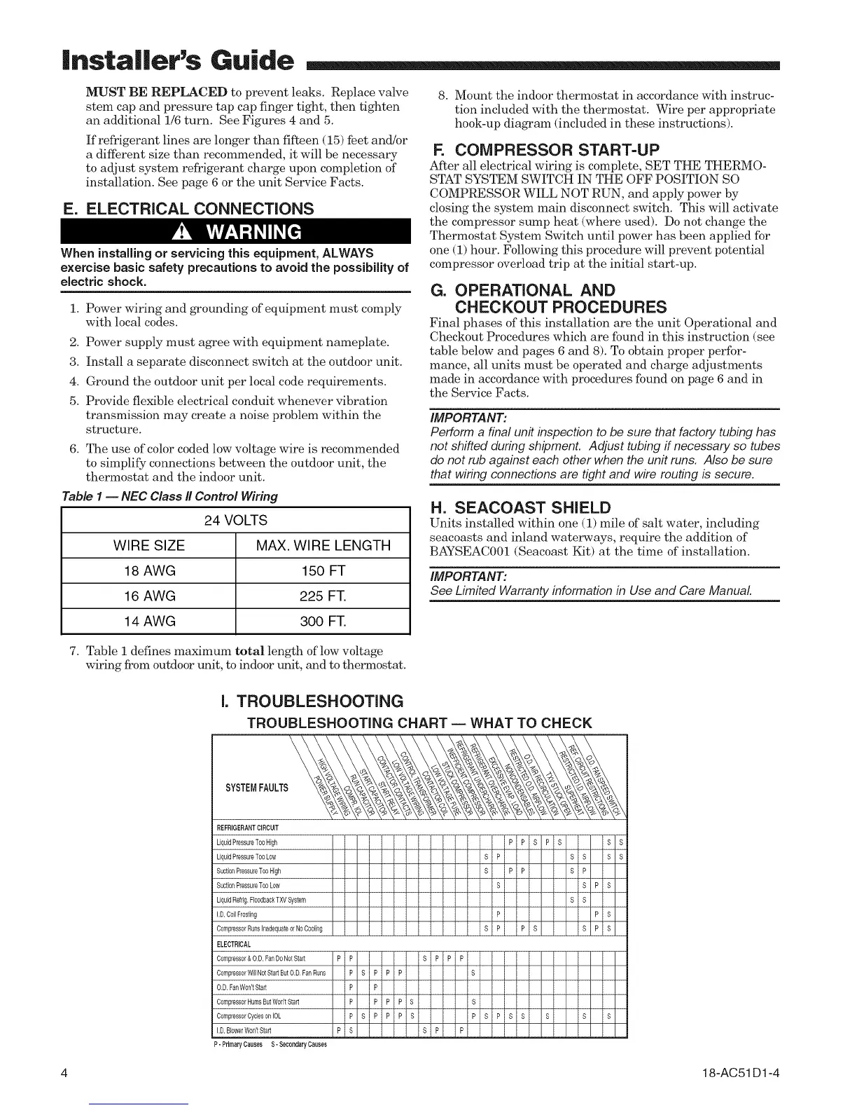
I. TROUBLESHOOTING
TROUBLESHOOTING CHART -- WHAT TO CHECK
SYSTEMFAULTS
REFRIGERANTCIRCUIT
LiquidPressureTooHigh
LiquidPressureTooLow
SuctionPressureTooNigh
SuctionPressureTooLow
LiquidRefrig,FloodbackTXVSystem
I,D,CoilFrosting
CompressorRunsInadequateorNoCooling
ELECTRICAL
Compressor&O,D,FanDoNetstar
CompressorNil NotStartButO,D,FanRuns
O,D,FanWon'tstar
CompressorHumsButWon'tStart
CompressorCyclesonIOL
I,D,BoleerWraPtStart
P- PrimaryCausesS-SecondaryCauses
i PiPSPS iS R
! sP i ss iss
i s PiP s P i
i R i SPiS
i i RS i
! P i PiS
i SP iPS SPiS
4 18-AC51 D1-4