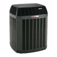
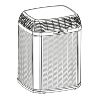
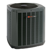
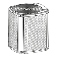
Do you have a question about the Trane 4TTV0061A1000A and is the answer not in the manual?
Warning about electrical hazards during servicing.
Warning about refrigerant oil hazards and handling.
Caution regarding hot surfaces on the unit.
Warning about refrigerant containment and pressure.
Importance of proper grounding for safety and equipment.
Warning about service valve operation and potential hazards.
Warning about proper brazing techniques and safety.
Warning about high leakage current and earth connection.
Table showing dimensions and weight of outdoor units.
Table detailing line sizes and valve connections for models.
Table showing alternate line sizes and valve connections.
Recommendations for optimal outdoor unit placement.
Precautions for units in cold climates with snow.
Requirements for units installed near saltwater.
Guidelines for proper installation of the support pad.
Determining required line length and lift for charging corrections.
Importance of insulating vapor and liquid refrigerant lines.
Precautions when reusing existing refrigerant lines.
Guidelines for routing refrigerant lines to minimize noise and vibration.
How to isolate refrigerant lines within wall spaces.
Methods for isolating refrigerant lines passing through walls.
Step-by-step instructions for brazing refrigerant lines.
Continued steps for brazing refrigerant lines, including tips.
Procedure for checking refrigerant lines for leaks using soapy solution.
Steps for evacuating refrigerant lines and indoor coil to a specific micron level.
Table of factory charge and multipliers for heat pumps.
Table of factory charge and multipliers for air conditioners.
Worksheet and steps for calculating charge for new installations.
Worksheet and steps for calculating charge for system repairs.
Procedure to open the gas service valve.
Procedure to open the liquid service valve, with warnings.
Table defining maximum wire length for low voltage control wiring.
Diagram for low voltage wiring connections in a communicating system.
Warning and guidelines for high voltage power supply.
Warning and procedure for installing a high voltage disconnect switch.
Explanation of LED states and their meanings on the control board.
Step-by-step guide for starting the system after installation.
Recommended temperature ranges for subcooling charge adjustment.
Worksheet and process for determining final subcooling value.
Chart for subcooling corrections for 2.0 ton units.
Chart for subcooling corrections for 3.0 ton units.
Chart for subcooling corrections for 4.0 ton units.
Chart for subcooling corrections for 5.0 ton units.
Chart for R-410A refrigerant charging based on liquid temperature and subcooling.
Procedure for adjusting refrigerant level based on gage pressure.
Steps to stabilize the system after adjustments.
Referencing pressure curves to verify system performance.
Fields to record system pressures and temperatures after charging.
Instructions for navigating the Communicating Display Assembly menus.
Overview of available technician menus: Monitor, Alert, History, Config, Control.
Explanation of how demand defrost operates and is measured.
How fault conditions are indicated by the CDA.
Inputs required for demand defrost to be enabled.
How defrost cycle initiation is calculated and adjusted.
Checklist for final system installation verification.


 Loading...