18-AC100D1-5D-EN 3
Section 2. Unit Location Considerations
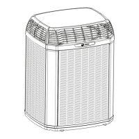
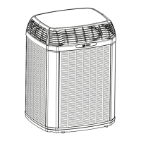
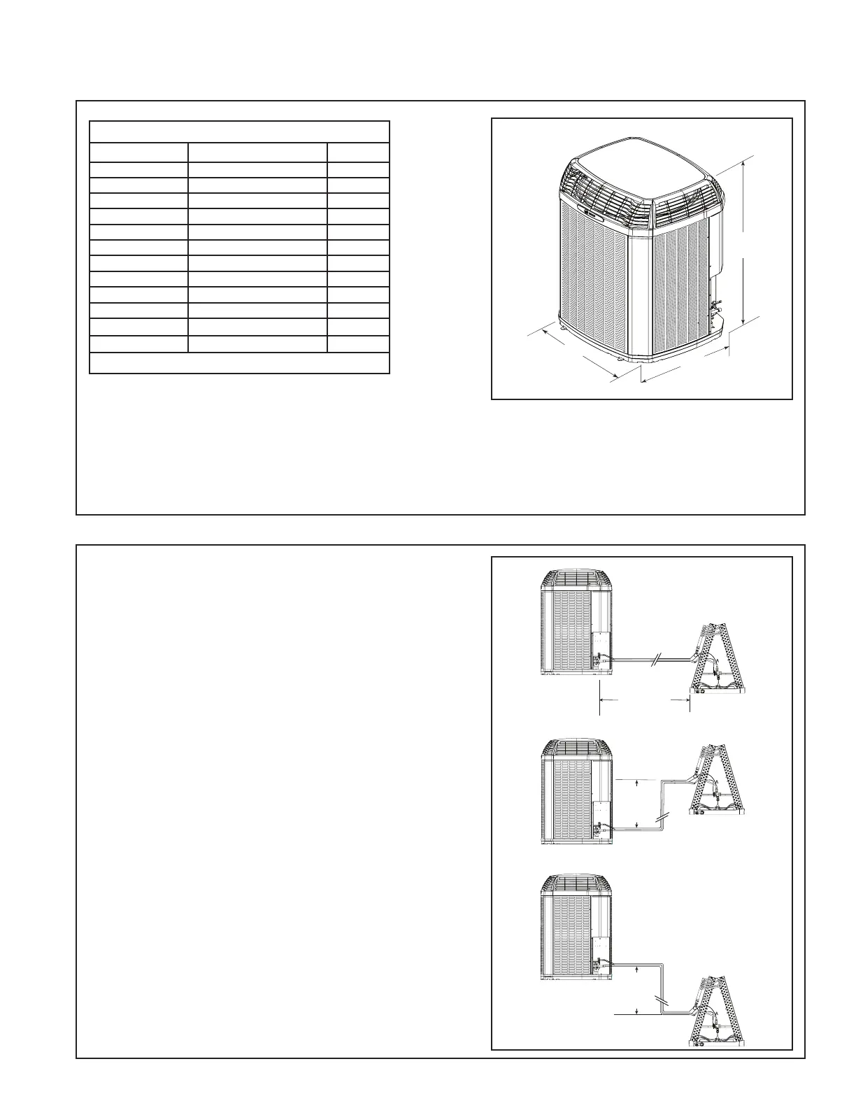
2.1 Unit Dimensions and Weight
2.2 Refrigerant Piping Limits
50’
Max
Vertical
Change
Standard
Line Set
150’ Max
TOTAL Line Length
50’
Max
Vertical
Change
Table 2.1
Unit Dimensions and Weight
Models H x D x W (in)
Weight* (lb)
4TTX6018J 35 x 30 x 33 172
4TTX6024J 35 x 30 x 33 173
4TTX6030J 42 x 30 x 33 195
4TTX6035J
35 x 30 x 33 167
4TTX6036J 44 x 34 x 37 221
4TTX6041J
44 x 34 x 37 221
4TTX6042J 52 x 34 x 37 277
4TTX6048J 52 x 34 x 37 281
4TTX6049J 52 x 34 x 37 281
4TTX6060J 52 x 34 x 37 286
4TTX6060K 52 x 34 x 37 271
4TTX6061J 52 x 34 x 37 301
* Weight values are estimated.
When mounting the outdoor unit on a roof, be
sure the roof will support the unit’s weight.
Properly selected isolation is recommended to
alleviate sound or vibration transmission to the
building structure.
Please refer to application bulletin for detailed
mounting information.
1. The maximum TOTAL length of refrigerant
lines from outdoor to indoor unit should
NOT exceed 150 feet (including lift).
2. The maximum vertical change should not
exceed 50 feet.
3. Service valve connection diameters are
shown in Table 5.1.
Note: For other line lengths, Refer to Refriger-
ant Piping Application Guide, SS-APG006-EN
or Refrigerant Piping Software Program, 32-
3312-03 (or latest revision).
 Loading...