EasyManua.ls Logo

Trane 4TWV0048A1000A - User Manual

Trane 4TWV0048A1000A
28 pages
To Next Page IconTo Next Page
Loading...
SSAAFFEETTYY WWAARRNNIINNGG
Only qualified personnel should install and service the equipment. The installation, starting up, and servicing of heating, ventilating, and
air-conditioning equipment can be hazardous and requires specific knowledge and training. Improperly installed, adjusted or altered
equipment by an unqualified person could result in death or serious injury. When working on the equipment, observe all precautions in the
literature and on the tags, stickers, and labels that are attached to the equipment.
October 2014
18-BC89D1-1D-EN
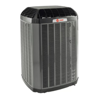
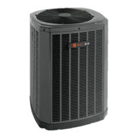
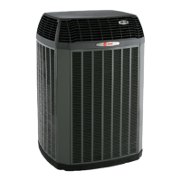
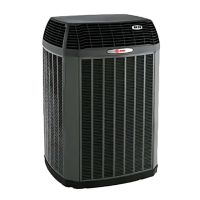
Variable Speed ComfortLink II
Heat Pumps and Air Conditioners
4TWV0024A1000A
4TWV0036A1000A
4TWV0048A1000A
4TWV0060A1000A
4TTV0024A1000A
4TTV0036B1000A
4TTV0048A1000A
4TTV0060A1000A
4TTV0061A1000A
Scan to see help
videos on this
product
NNoottee:: “Graphics in this document are for representation
only. Actual model may differ in appearance.
Installers Guide
Question and Answer IconNeed help?

Do you have a question about the Trane 4TWV0048A1000A and is the answer not in the manual?

Trane 4TWV0048A1000A Specifications

General IconGeneral
Model Number4TWV0048A1000A
CategoryHeat Pump
Cooling Capacity (BTU/h)48000
Cooling Capacity (tons)4
Heating Capacity (BTU/h)48000
Heating Capacity (tons)4
SEER Rating16
Refrigerant TypeR-410A
Voltage (V)208/230
Phase1

Summary

Safety Section

Outdoor Unit Safety Precautions

Covers hazards like high voltage, refrigerant, hot surfaces, and proper grounding.

Unit Location Considerations

Coastal Installation Considerations

Guidelines for installing units near salt water or seacoasts.

Unit Preparation and Setup

Outdoor Unit Setup and Pad Installation

Instructions for preparing and placing the unit on a support pad.

Refrigerant Line Considerations

Refrigerant Line Brazing Procedures

Refrigerant Line Leak Check and Evacuation

Refrigerant Line and Indoor Coil Evacuation

Procedures for checking refrigerant lines for leaks and evacuating the system.

Charging: Weigh-In Method

Service Valve Operation

Electrical Connections

Low Voltage Wiring Guide

Guidelines for low voltage wiring, including diagrams and maximum lengths.

High Voltage Power and Disconnects

Safety and installation requirements for high voltage power supply and disconnect switches.

Control Board LED Indicators

System Start Up Procedure

System Charge Adjustment

Subcool Charging Correction Charts

Unit Charging and Verification

Communicating Display Assembly (CDA)

Defrost Control (Heat Pump Only)

Demand Defrost Operation

Explanation of demand defrost operation, initiation, and termination.

Defrost Control Logic and Faults

Covers defrost enable, initiation criteria, and fault identification.

Final Checkout Procedures

Related product manuals