10
18-GF79D1-1A-EN
Refrigerant Leak Detection System
For all tables contained in this section of the manual,
the refrigerant charge is the total system charge which
is marked on the system according to the instructions
provided by the manufacturer of the outdoor unit.
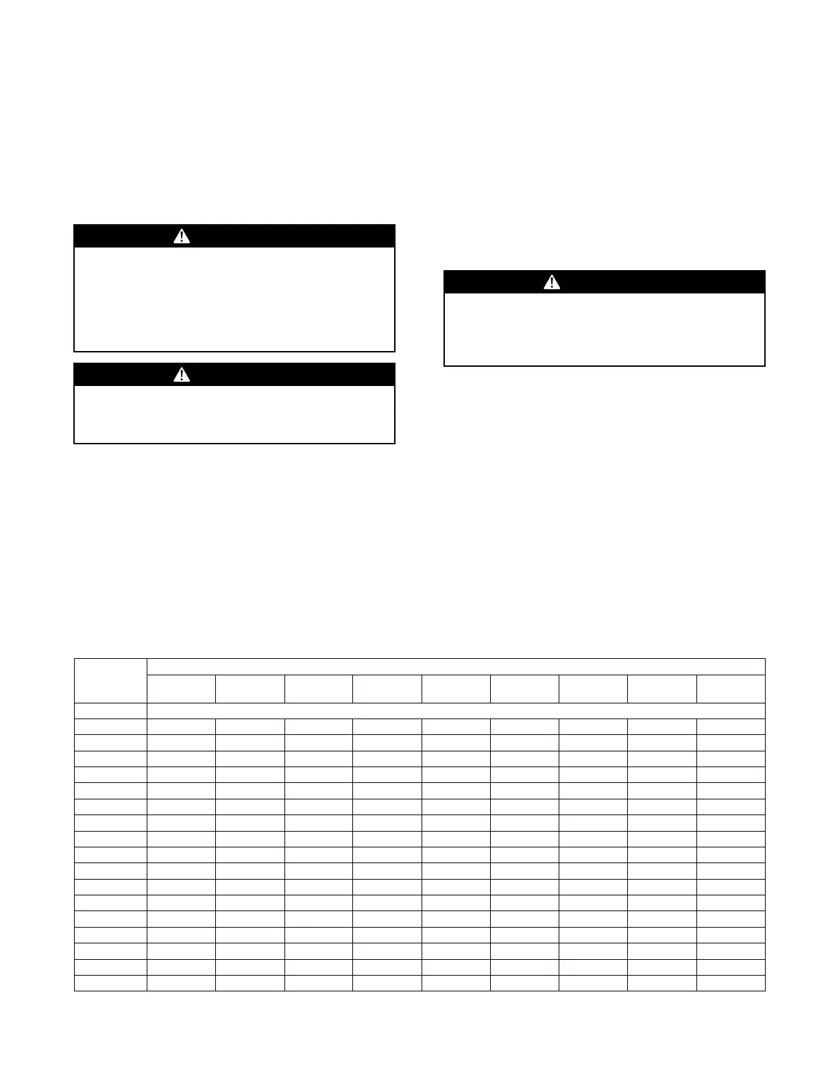
WWAARRNNIINNGG
RRiisskk ooff FFiirree!!
FFllaammmmaabbllee rreeffrriiggeerraanntt uusseedd.. TToo bbee rreeppaaiirreedd oonnllyy
bbyy ttrraaiinneedd sseerrvviiccee pprrooffeessssiioonnaall.. DDoo nnoott ppuunnccttuurree
rreeffrriiggeerraanntt ttuubbiinngg..
DDiissppoossee ooff pprrooppeerrllyy iinn aaccccoorrddaannccee wwiitthh ffeeddeerraall oorr
llooccaall rreegguullaattiioonnss.. FFllaammmmaabbllee rreeffrriiggeerraanntt uusseedd..
WWAARRNNIINNGG
LLEEAAKK DDEETTEECCTTIIOONN SSYYSSTTEEMM!!
LLEEAAKK DDEETTEECCTTIIOONN SSYYSSTTEEMM iinnssttaalllleedd.. UUnniitt mmuusstt bbee
ppoowweerreedd eexxcceepptt ffoorr sseerrvviiccee..
To ensure safety of the building occupants, the air
handler is equipped with a refrigerant leak detection
system. The system is comprised of a refrigerant
sensor and a mitigation control board. The system
automatically detects leaks in the indoor coil and
initiates actions to mitigate the risk of ignition of the
leaked refrigerant, including:
• Turning on the blower of the indoor unit to dilute
leaked refrigerant;
• Fully opening any zoning dampers, when
applicable;
• Turning off the compressor of the outdoor unit;
• De-energizing potential sources of ignition
connected to the system;
• Energizing an audible alarm, if so equipped.
Examples of potential ignition sources that are de-
energized include electrostatic air cleaners.
WWAARRNNIINNGG
RRiisskk ooff FFiirree!!
IIff iinnssttaalllliinngg tthhee uunniitt iinn aannyy ootthheerr oorriieennttaattiioonn ootthheerr
tthhaann uuppffllooww,, tthhee rreeffrriiggeerraanntt sseennssoorr mmuusstt bbee
rreellooccaatteedd.. SSeeee UUnniitt CCoonnvveerrssiioonn IInnssttrruuccttiioonnss,, pp.. 2288..
Refrigerant sensors for refrigerant leak detection
systems shall only be replaced as specified by the
manufacturer.
Minimum Conditioned Space
The installer must verify that the total space
conditioned by the system is large enough to safely
dilute any leaked refrigerant in the event of a
refrigerant leak of the indoor coil.
The minimum space conditioned by the appliance shall
be according to Table 3, p. 10. The conditioned space
includes any parts of the space connected via an air
duct system. The altitude of installation is the altitude
above sea level of the site where the equipment is
installed.
Table 3. Minimum Space Conditioned by the Appliance
Altitude (ft)
sea level-
2,000
2,001-
4,000
4,001-
6,000
6,001-
8,000
8,001-
10,000
10,001-
12,000
12,001-
14,000
14,001-
15,000
above
15,000
Charge (lb) Minimum Conditioned Space (ft
2
)
4 63 66 70 74 79 85 91 94 98
5 79 83 88 93 99 106 113 118 122
6 95 100 105 112 119 127 136 141 147
7 110 116 123 130 138 148 159 165 171
8 126 133 140 149 158 169 181 188 196
9 142 149 158 167 178 190 204 212 220
10 158 166 175 186 198 211 227 235 245
11 173 183 193 205 218 232 249 259 269
12 189 199 211 223 237 254 272 282 294
13 205 216 228 242 257 275 295 306 318
14 221 232 246 260 277 296 318 330 343
15 236 249 263 279 297 317 340 353 367
16 252 266 281 298 317 338 363 377 392
17 268 282 298 316 336 359 386 400 416
18 284 299 316 335 356 380 408 424 440
19 299 315 333 353 376 402 431 447 465
20 315 332 351 372 396 423 454 471 489