28
18-GF79D1-1A-EN
Unit Conversion Instructions
WWAARRNNIINNGG
RRiisskk ooff FFiirree!!
IIff iinnssttaalllliinngg tthhee uunniitt iinn aannyy ootthheerr oorriieennttaattiioonn ootthheerr
tthhaann uuppffllooww,, tthhee rreeffrriiggeerraanntt sseennssoorr mmuusstt bbee
rreellooccaatteedd..
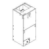
HHoorriizzoonnttaall LLeefftt SSeennssoorr RReellooccaattiioonn
Follow the conversion steps when installing the air
handler in horizontal left configuration.
1. Remove the front panels from the air handler. The
coil and line set panel do not need to be separated.
2. Pull refrigerant sensor and clip up and away from
the primary drain pan and remove it from the pan.
Secure sensor to secondary pan using provided
clip. Sensor should be positioned close to
secondary drain lines.
3. Position extra wire length in the secondary drain
pan.
Figure 6. All Models
4. Replace all panels.
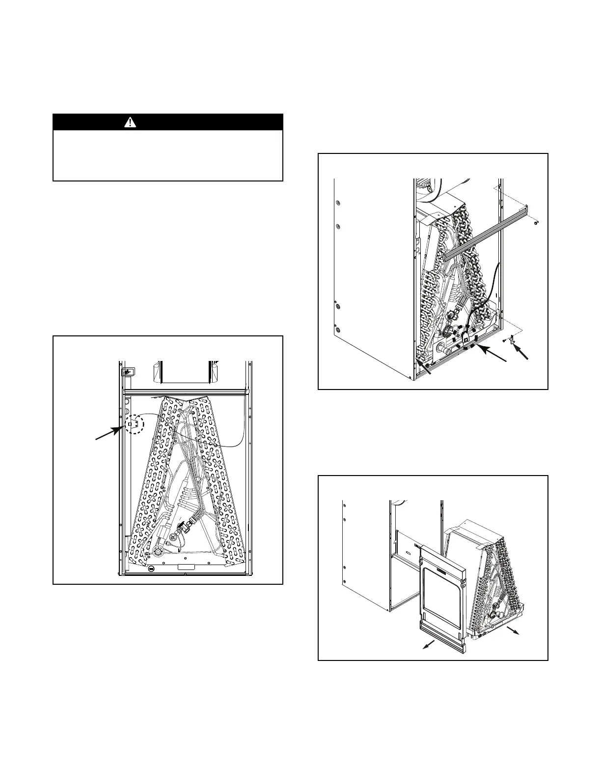
DDoowwnnffllooww
Follow the conversion steps when installing the air
handler in downflow configuration.
1. Remove the front panels panel from the air handler.
The coil and line set panel do not need to be
separated.
2. Remove the fasteners on both sides of the coil.
3. Remove the two screws holding the center
horizontal bracket and rotate out of place. Retain
parts.
Figure 7. All Models
4. Pull refrigerant sensor up and away from the
primary drain pan and remove it from the pan.
Detach the sensor and clip from the wire harness
and move it out of the way.
5. Slide the coil assembly out. Remove and discard
the horizontal drain pan.
Figure 8. All Models
6. On both sides of the cabinet, remove the screws
that hold the coil support brackets and retain for
later use. Seal the holes to prevent air leakage.