18-GF79D1-1A-EN
29
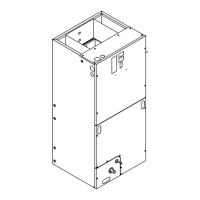
7. Rotate and lift the two coil support brackets to
remove from front slots in cabinet.
Figure 9. All models
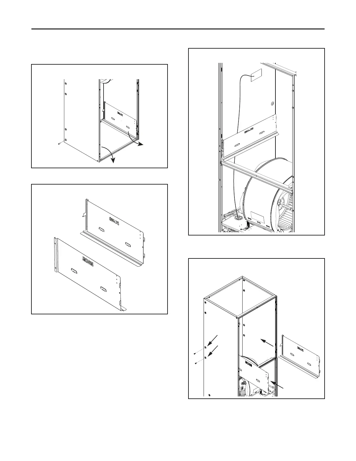
Figure 10. All models
8. Rotate the unit into the downflow orientation.
9. Pre-drill four clearance holes in the cabinet at
dimples located below the location the screws were
removed for the coil support brackets. There are
two holes per side. See location of holes.
10. Replace the center horizontal bracket removed in
Step 3. Use the screws retained from Step 3 to
attach.
11. Place coil support brackets into the slots and rotate
into place. Push downward to lock into place.
Refrigerant sensor wire harness should be routed
between coil support bracket and the insulation.
Figure 11. All Models
12. Secure each bracket with the screws that were
previously removed.
Figure 12. All models
UUnniitt CCoonnvveerrssiioonn IInnssttrruuccttiioonnss
 Loading...