18-GF79D1-1A-EN
11
Airflow Adjustment
NNoottee:: All 5TEM6 model air handlers have been factory
configured to provide sufficient airflow to dilute
leaked refrigerant.
Verification of Mitigation
Actions
After installation, the installer must verify that the
refrigerant leak detection system actuates all mitigating
actions listed above.
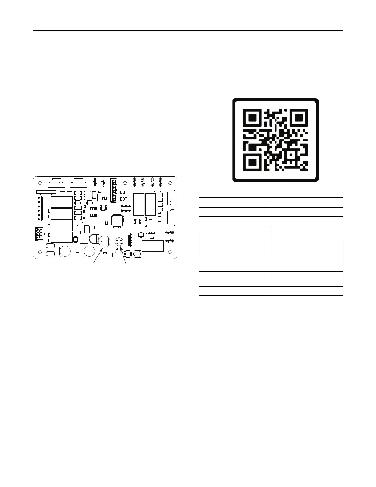
The test can be initiated by shorting the two test pins
on the header of the mitigation control board inside of
the unit. The mitigating actions will continue for
approximately 5 minutes. See Figure 1, p. 11 below.
Figure 1. AHC Board
Short these pins to test the
refrigerant detection system
Amber and Green LED
diagnostic indicators
If any of the mitigating actions are not actuated by the
system during the test, please check the following:
• All field wiring connections should be checked
against the diagrams in the “Field Wiring
Diagrams,” p. 17 section of this manual.
• The diagnostic indicators on the mitigation control
board should be checked against the diagnostic
codes given in below.
• Scan the QR code below for more information on
field troubleshooting of the refrigerant leak
detection system.
Table 4. MCB Diagnostic Code Table
Condition Green LED
Idle or Off Off
Startup
On
No Active Alarm Slow Flash
Active Alarm (Refrigerant
Leak, Sensor Communication
Error, or Sensor Error)
3 Flash
Past Refrigerant Detected
Alarm
4 Flash
Past Sensor Communication
Error
5 Flash
Past Sensor Error 6 Flash
RReeffrriiggeerraanntt LLeeaakk DDeetteeccttiioonn SSyysstteemm