I
d
L
Ht TP5
CP1 TP7
COF Tp1
DFT TP3
A951X
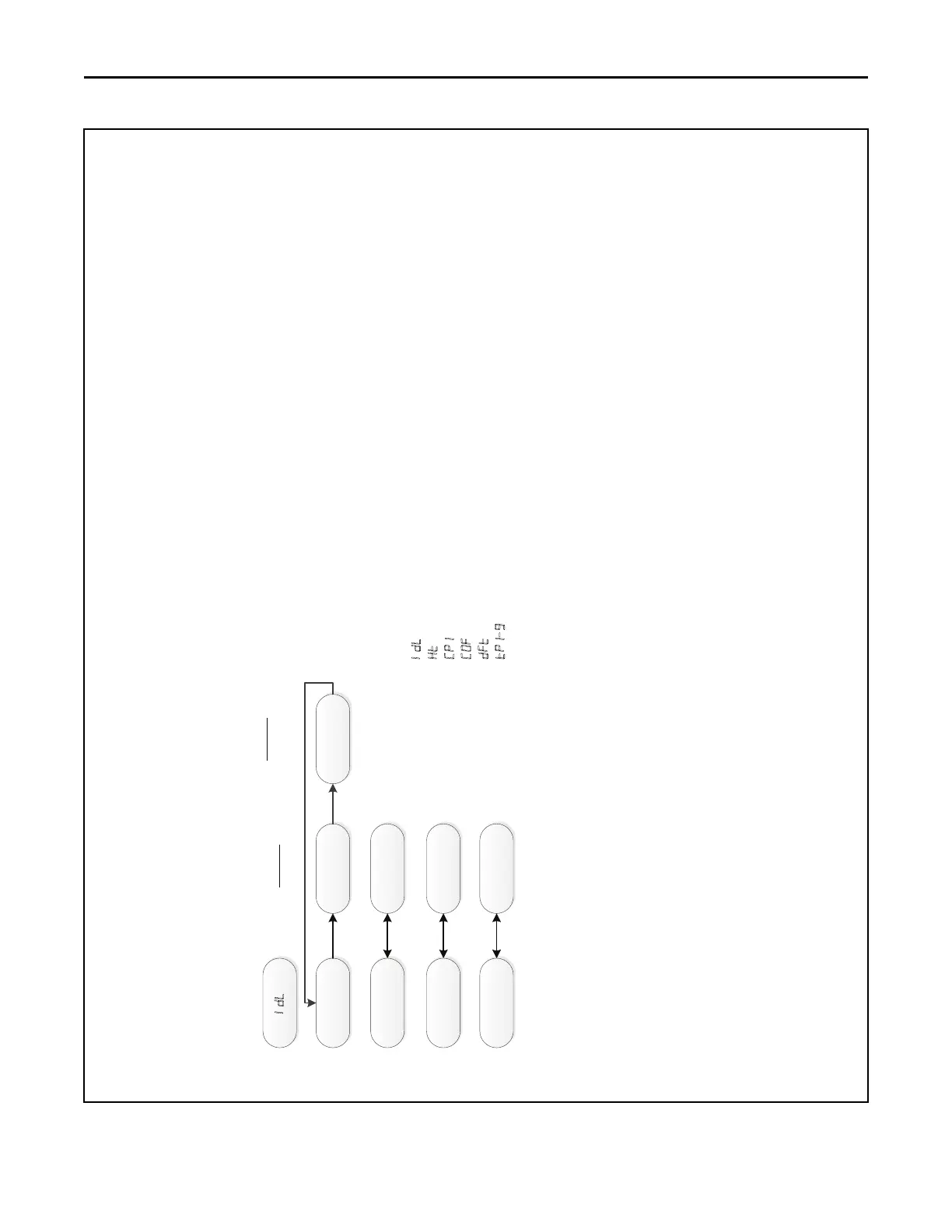
System Status Menu
IDL = Idle, no demand for cooling, heating, or fan
Ht = Demand for gas heat
CP1 = Demand for compressor cooling / Heat pump
COF = Demand for continuous fan
DFT = Demand for outdoor unit defrost, furnace running in gas heat mode
TP1-9 = Tap selected for airflow
NOTE:
(1) The menu status displayed is solely dependent on the input of 24VAC that is
applied to the low voltage terminal strip.
(2) The status will alternate between the system mode and the airflow request every 2
seconds.
(3) If an error occurs, an E*.* will alternately flash with the system mode and airflow
request. See first example
Example
Tap #5
e3.1
Example
Pressure
Switch Error