4
Section 2. Unit Design
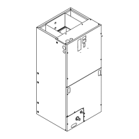
2.1 Cabinet Penetration
Screws can be drilled
into bottom of unit.
(1/2” max. screw length)
(Typical all sides)
Screws, saw cuts, and
other penetrations
are allowed in the
blower section for
installation of Side
Return Kit.
(Typical both sides)
Screws are allowed up to 3- 3/4”
from the top of the cabinet
(heater compartment).
(Typical both sides)
it
attachment are allowed
along the interior of
the cabinet (see arrows)
(Typical all sides)
No penetrations
allowed.
(Typical all sides)
Screws allowed only in
the rst 3/4” of front
bottom of unit (in cross
member)
Important: Due to the unique design of this unit,
which allows the electrical wiring to be routed within
the insulation, do not screw, cut, or otherwise punc-
ture the unit cabinet in any location other than the
ones illustrated.
Important: Under no conditions should metal strap-
ping be attached to the unit to be used as support
mechanisms for carrying or suspension purposes.
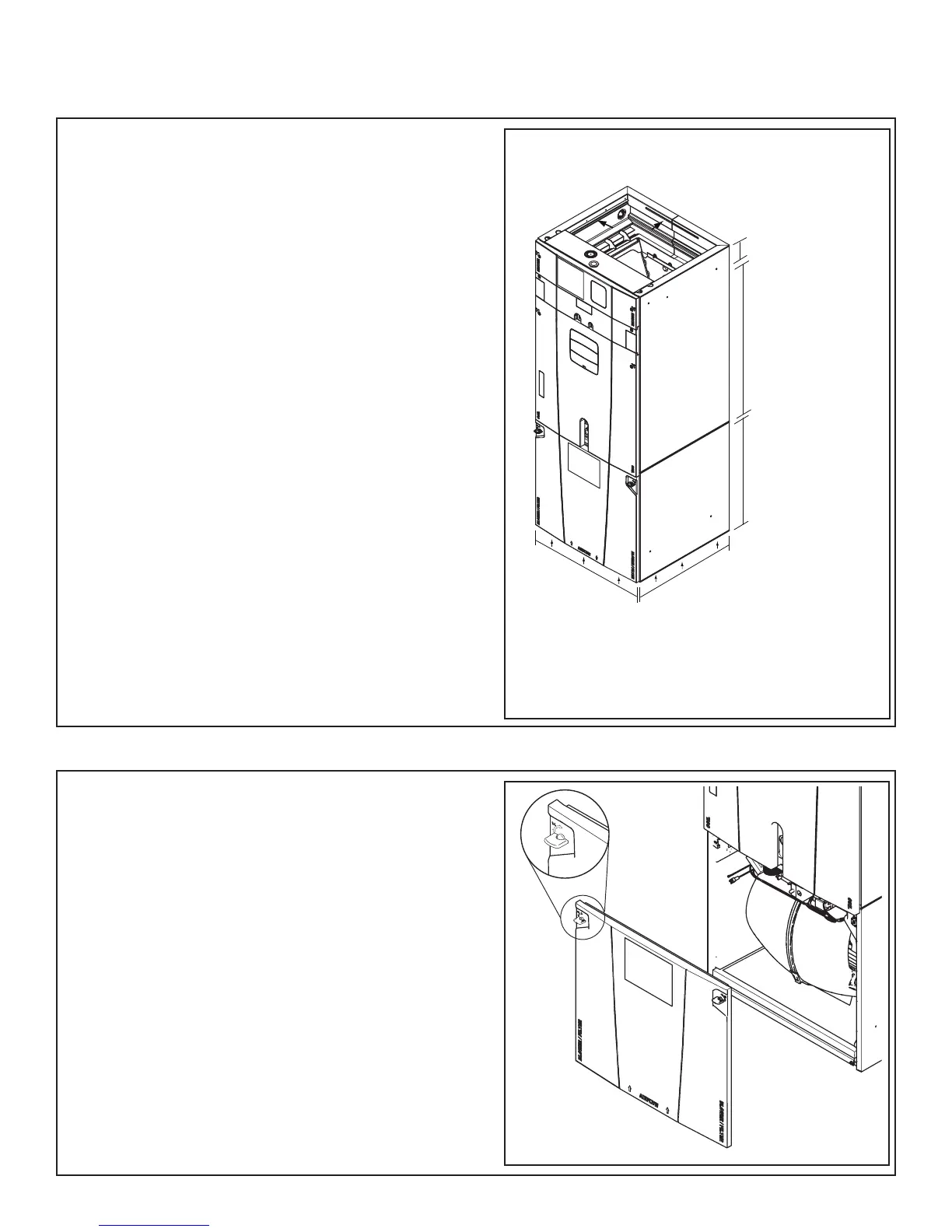
2.2 Panel Removal
The unit contains four (4) access panels: Blower/Fil-
ter, Coil, Line Set, and Heater.
The Blower/Filter panel is removed using 1/4 turn
thumb screws.
1. Turn thumb screws on Blower/Filter panel.
2. Pull top of panel out, away from cabinet.
3. Lift panel up out of channel.
4. Set aside.
 Loading...