HAZARDOUS VOLTAGE - DISCONNECT POWER BEFORE SERVICING
WARNING:
ALL phases of this installation must comply with NATIONAL, STATE AND LOCAL CODES
IMPORTANT — This Document is customer property and is to remain with this unit. Please return to service information
pack upon completion of work.
Installer’s Guide
1
MOUNTING CONTROL BOARD
COOLING ONLY AIR CONDITIONER
HEAT PUMP
Low Ambient Control Kit
BAYLOAM103
HDPC-IN-18B
18-HE46D1-3
LOW AMBIENT KIT CONTENT:
1 - Controller Module
1 - Liquid Line Temperature Sensor
1 - Outdoor Air Temperature Sensor
1 - B Y O Low Voltage Wiring Harness
1 - Sensor Clamp
1 - Thermal Grease
1 - Insulation Tape
1 - Information Label
3 - Screws, Wire Nuts, Wire Ties
1 - Installer’s Guide.
INSPECTION:
Check carefully for any shipping damage. This must be re-
ported to and claims made against the transportation company
immediately. Any missing parts should be reported to your
supplier at once and replaced with authorized parts only.
INSTALLATION:
NOTE:
As the head pressure control is applied to units operating
in low ambient conditions, it is required that the units have
compressor crankcase heaters and non-bleed txv’s.
Refer to the Low Ambient Application documentation.
ATTACH INFORMATION LABEL
Attach the Information Label to the control box cover. This label,
identifies fan motor cycling during low ambient operation.
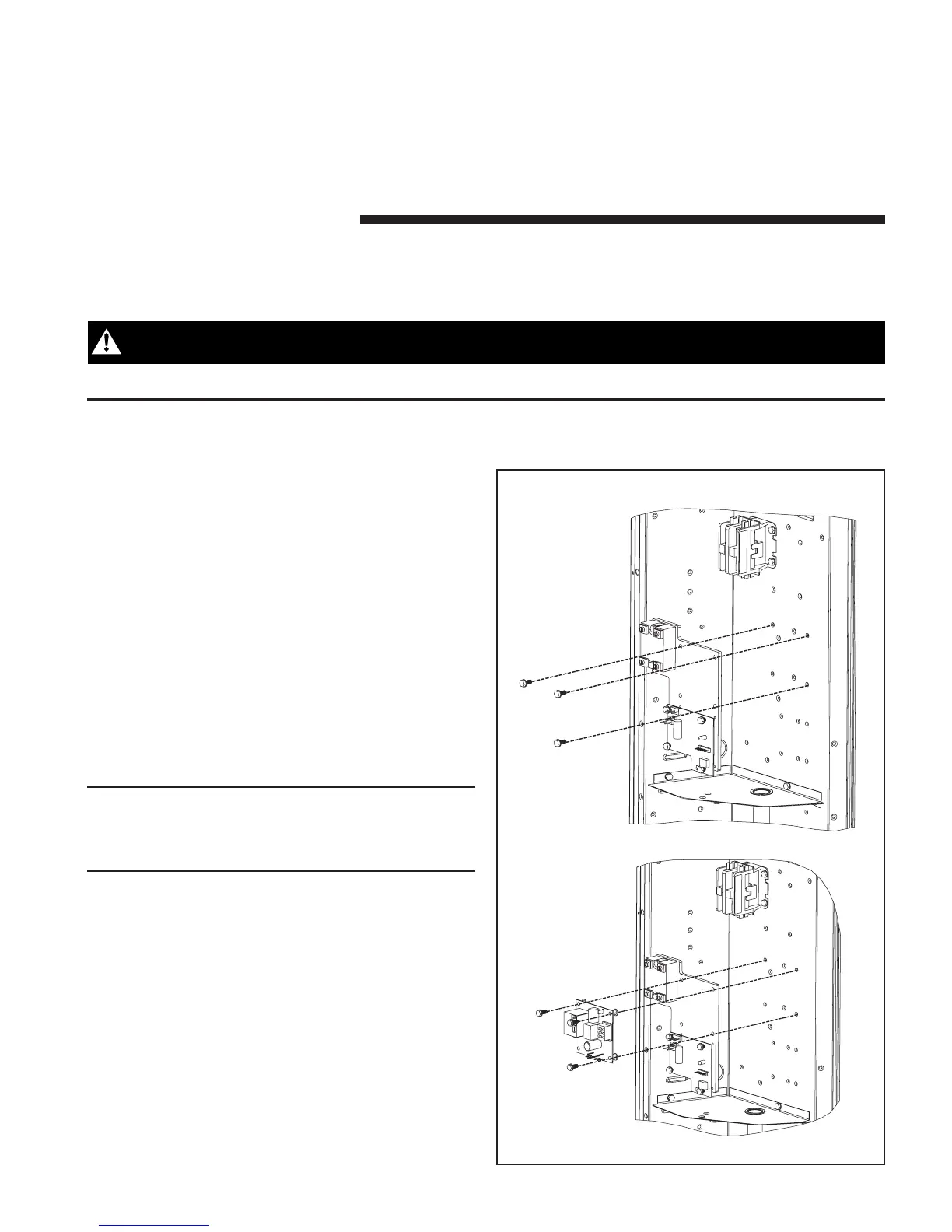
MOUNTING CONTROL MODULE
1. Be certain power to unit is DISCONNECTED.
2. Remove cover panel on control box compartment.
3. Install control module into the control box.
a. If installing into an air conditioner only unit (non-
heat pump), use the three (3) screws provided and
attach to the control box as illustrated in Figure 1.
b. If installing into a heat pump unit, remove the
three (3) screws holding the defrost board, place low
ambient kit assembly behind the defrost board and
reattach the defrost board and low ambient control
with the three (3) screws provided in the original
defrost board mounting location. See Figure 1.
 Loading...