© 2004 American Standard Inc. All Rights Reserved 18-HE46D1-3
Installer’s Guide
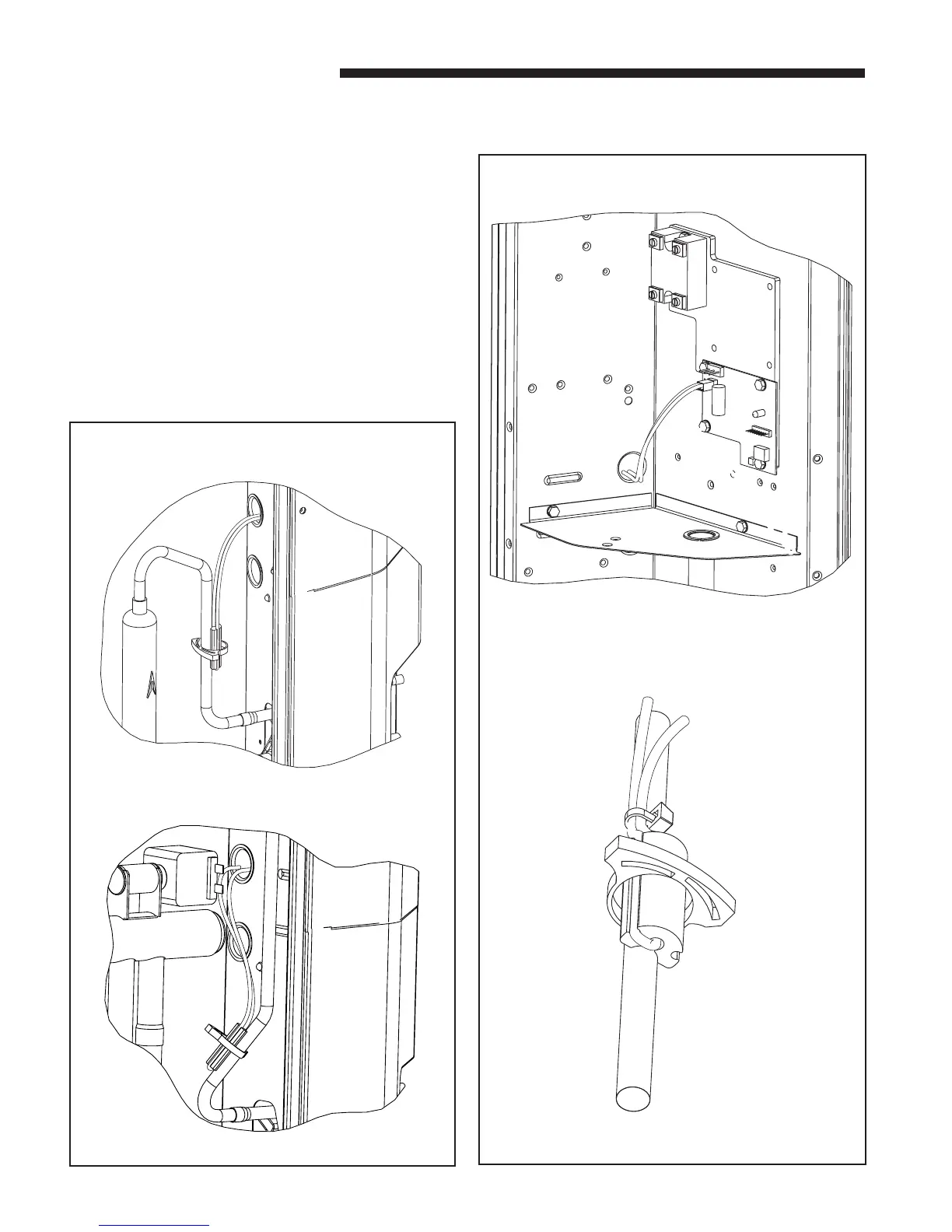
MOUNTING LIQUID LINE TEMPERATURE SENSOR
4. Remove the service access panel to the left side of the
control box of the air conditioner or heat pump.
5. Attach the liquid line sensor to the liquid line:
a. If installing on a cooling only air conditioner unit,
attach the liquid line sensor to the liquid line near the
drier assembly. Apply thermal grease (supplied) to the
liquid line, where the sensor will be mounted. Using
the clamp provided, attach the sensor as shown;
Figure 2A. When completed, wrap the complete
assembly with the insulation tape.
b. If installing on a heat pump unit, attach the liquid
line sensor to the liquid line running vertically,
directly behind the control box. Apply thermal grease
(supplied) to the liquid line, where the sensor will be
mounted. Using the clamp provided, attach the sensor
assembly as shown; Figure 2B. When completed, wrap
the complete assembly with the insulation tape
provided.
6. Route the sensor leads through the low voltage access
hole and attach to the two (2) pin connector provided on
the control board. See Figure 3.
B) HEAT PUMP
A) COOLING ONLY AIR CONDITIONER
CONTROL BOX SENSOR WIRING ROUTING
2
3
APPLY CLAMP TO SENSOR AND LIQUID LINE
LIQUID LINE TEMPERATURE SENSOR
 Loading...