18-HE46D1-3 3
Installer’s Guide
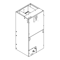
MOUNTING OUTDOOR TEMPERATURE SENSOR
7. Using pliers, bend the corner of the control box base
downward, to create an opening for the sensor leads. See
Figure 4.
8. Route the sensor, from the control board, down through
the opening created in the control box base. With wire tie
provided, secure the sensor to the low voltage wiring or
conduit below the control box base. Place the wire tie on
the sensor wires (not on the sensor) and dress so that the
temperature sensing area is not in direct contact with
any surrounding surfaces and is not in direct sunlight.
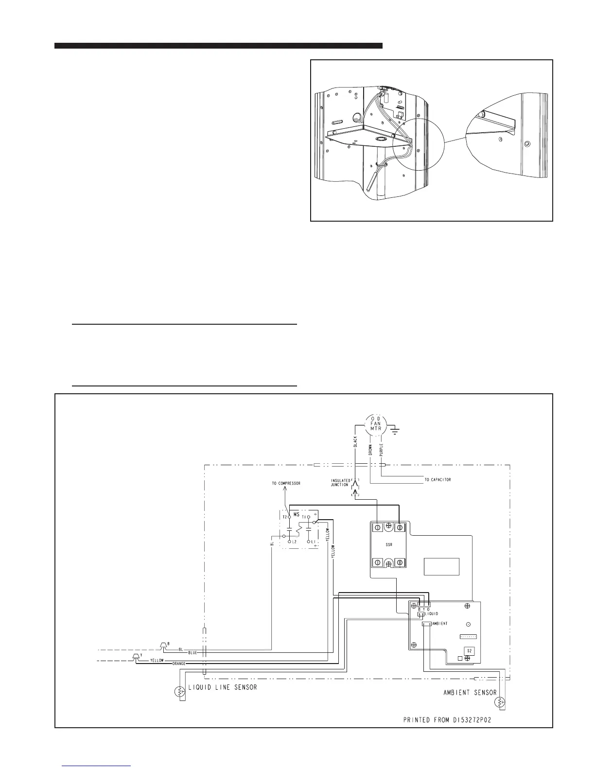
WIRING CONTROL MODULE
9A) Cooling Only Air Conditioner Models: See Figure 5
Disconnect the black fan motor lead from the contactor
(This wire is attached to contactor terminal “T2”, with a
quick connect terminal). Reconnect this fan motor lead to
the black wire from the solid state relay on the control
module. This wire has a sleeved, 1/4" male tab for
attaching to the fan motor wire terminal.
Connect the other black wire from the solid state relay to
the contactor terminal “T2” (from where the fan motor
lead was disconnected).
Low voltage wires:
Connect the 3-pin wire assembly to J5 on the control
board (3-pin male connector).
NOTE:
To ease the insertion of the connector housing onto
the J5 header, place the connector on the tips of the
three header pins. Angle the connector upward toward
the header latch while pushing connector over the
header pins.
Connect the yellow lead wire to a 1/4" male tab on the
right hand side of the main contactor (low voltage
contactor coil terminal).
Connect the blue lead wire to the wire nut junction of the
blue wire.
Connect the orange wire to the wire nut junction of the
yellow wire.
(New wire nuts are provided)
4
OUTDOOR TEMPERATURE SENSOR
BEND CONTROL
BOX CORNER
SENSOR WIRE ROUTING
5
AIR CONDITIONING / COOLING ONLY
 Loading...